Well, I have increased the length of the window, the sampling rate in the window, and if the accuracy was due to either of these limited the accuracy of the THD, I would think that the THD would continue to change as the sampling time or sampling rate was changed. The method is to inject a sine wave a particular frequency and do Fourier analysis of the harmonics. Any truncation error due to the window should be reduced as the window interval is increased. Perhaps there's another way to do it?
I’ll take a deep breath tomorrow and enter your circuit diagram in LTSpice.
We’ll see what that brings.
Hans
We’ll see what that brings.
Hans
Are your short circuit protection transistors turning on?
They can introduce distortion if not kept off properly. Try simulating without them?
They can introduce distortion if not kept off properly. Try simulating without them?
Well, I have increased the length of the window, the sampling rate in the window, and if the accuracy was due to either of these limited the accuracy of the THD, I would think that the THD would continue to change as the sampling time or sampling rate was changed. The method is to inject a sine wave a particular frequency and do Fourier analysis of the harmonics. Any truncation error due to the window should be reduced as the window interval is increased. Perhaps there's another way to do it?
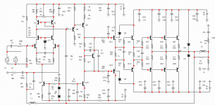
I have simulated your model in LTSpice, with 4*34mA bias current.
Not knowing what low power transistors you have used, I took resp. the 2N3904/2N3906.
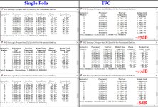
For single pole I used a 100pF Miller cap and for TPC two times 200pF with 2K + 100nF in the middle to gnd.
The 100nF cap is to suppress a peak at 1.5Khz in the loop gain.
See first image below what TPC did to the loop gain compared to single pole.
To show the impact of TPC even further, I used a 4R instead of a 8R load resistor and measured with 22V rms out or 120Watt into 4R the distortion at 1kHz, 3Khz and 10Khz.
Distortions are listed below.
Improvement for TPC was between 8dB and 17dB.
Hans
Attachments

Do you have a guess as to how this affects stability and oscillation? I have always been concerned about schemes with a steeper phase slope around the unity gain frequency that they could be pushed more easily into oscillation, especially by a capacitive load.
Based on your results, it seems easy enough to add TPC to the circuit. The main drawback would be that constructors would need to know to omit the resistor and short a capacitor for single pole Miller compensation. I'll work on reproducing your results.
Based on your results, it seems easy enough to add TPC to the circuit. The main drawback would be that constructors would need to know to omit the resistor and short a capacitor for single pole Miller compensation. I'll work on reproducing your results.
To get a better feeling about stability is best done by offering a square wave and look at the overshoot that should be acceptable.
And no, in single pole mode one only has to omit the resistor in between, no cap shortening at all because 2 times 200pF in series is exactly the 100pF that you need in single pole.
And no, in single pole mode one only has to omit the resistor in between, no cap shortening at all because 2 times 200pF in series is exactly the 100pF that you need in single pole.
I modeled your scheme.Q9 is closed,not working .I didn't put it in the diagram.The output stage made a triple and without protection..Diagram and model in MS-12 in the attachment.
I'll post the meander and frequency analysis if necessary
I'll post the meander and frequency analysis if necessary
Attachments
Last edited:
It seems you used Hayk’s idea to break the feedback loop above a certain frequency, but then you could also break the Miller loop to have the full benefit.
Hans
Hans
IMDIt seems you used Hayk’s idea to break the feedback loop above a certain frequency, but then you could also break the Miller loop to have the full benefit.
Hans
Attachments

Last edited:
Thank you both for the simulations. I have added TPC to the design and eliminated Q9 to make space for it, because in building it I think Q9 is sometimes causing the VAS to overload current and burn out Q8.
Much appreciated, you’re welcome.
In these days it seems that saying thank you when someone did a lot of work for you becomes less and less the norm.
Hans
In these days it seems that saying thank you when someone did a lot of work for you becomes less and less the norm.
Hans
profdc9 - the problem with Q9 is that your original circuit showed Q8 did not have any protection. Q9 is a protection transistor, so as stanislav pointed out, does nothing normally. But Q8 needs a limiting resistor in case it turns on. Typically 1k. Hans I think had 4.7k. Actually, my simulator in a similar circuit did not calculate the DC op point correctly unless there was a resistor in place. A sort of early warning!
I am making the design available on github, with PCBs, gerbers, softstart, XLR to unbalanced (based on THAT1200/INA134/SSM2141), power conditioning, etc. available as a complete DIY open source design, so thanks to you and your work it will be better as a result.
I have already built the circuit up and it works now and sounds pretty good but I am still hunting down a source of ground loop hum when I connect it to the preamp.
You can take a look at what I have so far at
GitHub - profdc9/PowerAmpAudio: Power Amplifier based on Michael Chua's C300 amplifier
The idea is to make a complete design for educational and archival purposes kind of like the Honey Badger but greatly simplify the design so that if in the future there are fewer transistor types available, especially if only the generic Chinese types are available, one can still find parts and build a decently performing amp.
Much appreciated, you’re welcome.
In these days it seems that saying thank you when someone did a lot of work for you becomes less and less the norm.
Hans
@profdc9
I think you should have a look over here.
It concerns an improved TPC version where your circuit diagram was used as a test vehicle, with dramatic improvements.
Hans
I think you should have a look over here.
It concerns an improved TPC version where your circuit diagram was used as a test vehicle, with dramatic improvements.
Hans
Sorry Hans, I do not understand. Was there a link or a comment that you were referring to that you suggest I should look at?
@profdc9
I think you should have a look over here.
It concerns an improved TPC version where your circuit diagram was used as a test vehicle, with dramatic improvements.
Hans
Sorry, here is the link that I forgot to include.
What is nested feedback, how it realy works and some examples...
Hans
What is nested feedback, how it realy works and some examples...
Hans
I am making the design available on github, with PCBs, gerbers, softstart, XLR to unbalanced (based on THAT1200/INA134/SSM2141), power conditioning, etc. available as a complete DIY open source design, so thanks to you and your work it will be better as a result.
I have already built the circuit up and it works now and sounds pretty good but I am still hunting down a source of ground loop hum when I connect it to the preamp.
Since you have a working amp designed for the purpose, it would be very informative if you could share your listening experience between Single Pole, TPC and OITPC.
Hans
Since you have a working amp designed for the purpose, it would be very informative if you could share your listening experience between Single Pole, TPC and OITPC.
Hans
I am interested too.🙂
- Home
- Amplifiers
- Solid State
- Simulating single pole vs. Transistional Miller Compensation (TMC)