Do you mean no difference between 100 ohm and 0 ohm (no hum in either case) or no difference between 100 ohm and no connection (hum in both cases)?
So at this point I am willing to implement this change for all coaxials, to see if the total circuit will perform ok.
I am concerned about the fact that there will be 10 ground loops, but fortunately the one I "cured" today was the farthest away, thus the bigger loop. So I am guessing that I have a high chance of succeeding. There is a "but" in this that I will explain later.
(A detail that may not matter is that this coaxial does not touch the chassis (I had accidentally cut it a bit shorter), but every other coaxial does. I will see if that makes any difference of course, but should it in theory?)
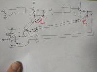
I attach a sketch of the situation with 2 coaxials. What I am saying is that I performed a test that worked for the right coaxial - which means the one with the greater loop area, but the one that "goes through" the last circuit in line, thus with the smaller sensitivity.
In that case, maybe I should try to "break" the loops with the 100 Ohm resistors (shown in red)? To minimize the current through them as MarcelvdG suggested.
I am concerned about the fact that there will be 10 ground loops, but fortunately the one I "cured" today was the farthest away, thus the bigger loop. So I am guessing that I have a high chance of succeeding. There is a "but" in this that I will explain later.
(A detail that may not matter is that this coaxial does not touch the chassis (I had accidentally cut it a bit shorter), but every other coaxial does. I will see if that makes any difference of course, but should it in theory?)
I attach a sketch of the situation with 2 coaxials. What I am saying is that I performed a test that worked for the right coaxial - which means the one with the greater loop area, but the one that "goes through" the last circuit in line, thus with the smaller sensitivity.
In that case, maybe I should try to "break" the loops with the 100 Ohm resistors (shown in red)? To minimize the current through them as MarcelvdG suggested.
Attachments
Do you mean no difference between 100 ohm and 0 ohm (no hum in either case) or no difference between 100 ohm and no connection (hum in both cases)?
No hum in either case.
For 5-20 cm long wires you may use just single wires, but not coaxial. Especially since you have low impedance (almost zero) at cable inputs.
Why not? They are just electrically short shielded cables. Just make sure their capacitance doesn't cause oscillations (which it used to do, but that has been solved).
In that case, maybe I should try to "break" the loops with the 100 Ohm resistors (shown in red)? To minimize the current through them as MarcelvdG suggested.
With reference to the schematic of post #34, you have a reason to want a switch in the ground, but having the domains float completely causes hum, possibly via the mechanism described in post #39. The best you can do then is to connect a resistor (100 ohm for example) in parallel with each ground switch.
Today I did the following experiment, that I hoped would solve my problem.
First, I connected the biggest coaxial's floating ground to the mixer's ground via a 100 Ohm resistor. I happened to have the mixer's ground on every pcb so I used it.
This worked like a charm. No hum was audible as a contribution of coaxial no10 in bypass.
This urged me to connect every coaxial's ground to the same point via a 100 Ohm resistor. So I did it on every pcb board.
Sadly, the problem was there again. AND, coaxial no10 was introducing hum again, as nothing happened, even though it worked well alone. Maybe this tells us something about the mechanism of the hum, but I am neither able not patient enough to detect it yet.
I will try another messy experiment, that is to keep these 10 new connections but disconnect the point they all go from the output mixer's ground.
I cannot believe how complicated this has become. If my experiment is not clear, I will be happy to draw a sketch.
Last edited:
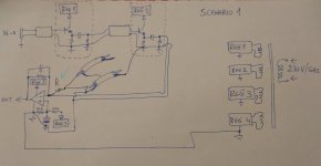
I decided to draw a sketch of the situation, to make things better.
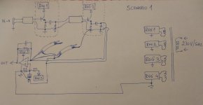
I tried Scenario_1, as we talked before, and the right coaxial that was grounded to REG2 according to the sketch, did not contribute any hum.
Then, to do the same thing for the other coaxial, I would have to connect the left coaxial's floating ground to REG1 ground.
I have NOT tried the above, since the cables connecting REG1 and REG2 ground that go through the second blank box will be meters in length, and the box may contain a very high gain circuit. So I thought that I should avoid routing a loop through such a circuit. MarcelvdG successfully suggested that I "create" such a loop in scenario 1 and it worked, but I thought it worked because the loop was directly before the mixing opamp, so there was no substantial gain to amplify its noise. Do you think it would be better than scenarios 2&3 nonetheless?
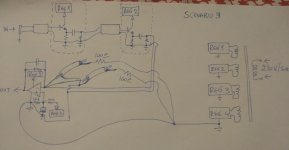
In Scenario_3, I received hum from every one of the coaxials.
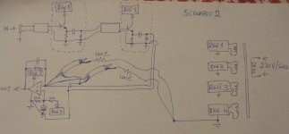
In Scenario_2, if I left only one coaxial connected through 100 Ohm to REG4 ground, it contributed no hum. But the moment I engaged another coaxial via a 100 Ohm resistor, the hum reappeared. And if I engaged no coaxials at all, I had hum at the output!
Could the following lead to the answer as far as the noise source is concerned? The 4 REGS come out of the same toroidal core, isolated of course and using LM317s to regulate their outputs.
I tried Scenario_1, as we talked before, and the right coaxial that was grounded to REG2 according to the sketch, did not contribute any hum.
Then, to do the same thing for the other coaxial, I would have to connect the left coaxial's floating ground to REG1 ground.
I have NOT tried the above, since the cables connecting REG1 and REG2 ground that go through the second blank box will be meters in length, and the box may contain a very high gain circuit. So I thought that I should avoid routing a loop through such a circuit. MarcelvdG successfully suggested that I "create" such a loop in scenario 1 and it worked, but I thought it worked because the loop was directly before the mixing opamp, so there was no substantial gain to amplify its noise. Do you think it would be better than scenarios 2&3 nonetheless?
In Scenario_3, I received hum from every one of the coaxials.
In Scenario_2, if I left only one coaxial connected through 100 Ohm to REG4 ground, it contributed no hum. But the moment I engaged another coaxial via a 100 Ohm resistor, the hum reappeared. And if I engaged no coaxials at all, I had hum at the output!
Could the following lead to the answer as far as the noise source is concerned? The 4 REGS come out of the same toroidal core, isolated of course and using LM317s to regulate their outputs.
Attachments
Last edited:
Is the next stage this circuit feeds DC blocked?
Also, your summer has the positive input tied to 7.5 volts, but the negative is tied to ground by a resistor. the opamp has to drive DC current through the feedback resistor sufficient to produce 7.5 volts at the negative input.
Also, you didn't draw in any way to setup the base voltage at half rail in the emitter followers. I assume there is something.
jn
Last edited:
Is the next stage this circuit feeds DC blocked?
jn
Yes, I drew the sketch without a cap for simplicity.
You have drawn your circuit two different ways. In one, you have a resistor to ground at the emitter follower, in another you have it in series with the cap. Which one is accurate?
If it is to ground as in your recent drawing, and it is a unity gain setup, the amp will try to set the output to 15 volts so the negative input is 7.5 volts with only one source connected. The opamp cannot reach positive rail. If you connect two, it is worse.
Also, in your post 34, you float the 2.2 uf cap when it is not selected, but the negative input is at a DC value of 7.5 volts. When the cap discharges, and then you select it, there will be a very large pop in the system.
jn
I have NOT tried the above, since the cables connecting REG1 and REG2 ground that go through the second blank box will be meters in length, and the box may contain a very high gain circuit.
Does this mean that there is always a connection between the grounds of the various blocks, although those connections may be quite long? That pretty much refutes my hypothesis about why there was hum in the first place.
Does this mean that there is always a connection between the grounds of the various blocks, although those connections may be quite long? That pretty much refutes my hypothesis about why there was hum in the first place.
Yes, I have designed the whole circuit to have common ground without ground loops. I just floated 10 coaxials into the inverting input of the output mixer, that's all. There is hum right there.
I believe that the source of hum may be found according to your logic though. Look at Scenario_2: when I floated the mixer ground with respect to REG4 ground, reconnecting it with loops resulted in hum, leaving it open (no connections between REG4 and mixer ground) resulted in hum too, only connecting it via one 100 Ohm resistor did the trick. Could this mean there is a hum coupling between REGS according to your thinking?
Audiostrat,
I note you have not responded to my posts.
If you feel that I am an annoyance, just tell me and I will not try to assist.
Jn
I note you have not responded to my posts.
If you feel that I am an annoyance, just tell me and I will not try to assist.
Jn
Audiostrat,
I note you have not responded to my posts.
If you feel that I am an annoyance, just tell me and I will not try to assist.
Jn
Of course I don't view you as an annoyance. I didn't manage to answer your posts yet.
I have drawn the schematics for simplicity without capacitors. Every stage is ac coupled (followers to mixer etc) and every stage (followers and mixer) are centre biased, as possible.
Regarding the pop it is not a problem, I am well aware of it but I have taken measures.
Cool. No worries.
I would have used neg regulators though, as I have enough problems with hum without worrying about the noise of a synthetic ground.
My thinking is along the lines of you're forcing the summer to fight to maintain plus and minus input D.C. Levels. And the system is having problems with that.
Jn
I would have used neg regulators though, as I have enough problems with hum without worrying about the noise of a synthetic ground.
My thinking is along the lines of you're forcing the summer to fight to maintain plus and minus input D.C. Levels. And the system is having problems with that.
Jn
No I haven't, and I initially did not put the resistors there because I feared that they might pick up noise (the irony 😛).
I am focusing on bypassing the cables with extra switches either way, but I will try your suggestion (another member proposed that I use some series resistance but to avoid RF oscillation I think).
I am focusing on bypassing the cables with extra switches either way, but I will try your suggestion (another member proposed that I use some series resistance but to avoid RF oscillation I think).
Cool. No worries.
I would have used neg regulators though, as I have enough problems with hum without worrying about the noise of a synthetic ground.
My thinking is along the lines of you're forcing the summer to fight to maintain plus and minus input D.C. Levels. And the system is having problems with that.
Jn
The virtual ground comes from a regulated power supply, I don't see how the mixer would fight to maintain it. Or I misunderstood your comment.
The opamp is trying to make the negative input be the exact same voltage as the positive input. If you have a resistor to ground at a source, the opamp will put 7.5 volts across it. That means the D.C. output has to be high enough that the divider puts 7.5 volts on the negative input. If Rsource equals Rfeedback, the output will be 15 volts D.C., rail.
That is why I noted the difference in the schematics.
Jn
That is why I noted the difference in the schematics.
Jn
- Home
- Design & Build
- Construction Tips
- Coaxial noise pickup