It helps using the standard terms for PE systems.
Erection of earthing arrangements (TNC, TN-S, TNC-S, TT) | EEP
Erection of earthing arrangements (TNC, TN-S, TNC-S, TT) | EEP
Hmm, having a look at the schematic I don't have a cap parallel to the feedback resistor... Because I used one at the following stage. I will add one tomorrow!
With 10 kohm and 220 pF in the feedback around an NE5532, the stability should be OK up to about 15 nF in total at the negative input. Some 150 pF already comes from the cables, assuming 50 ohm coax, or 420 pF when it is cheap shielded cable with PVC dielectric.
Without the 220 pF and without series resistor, it is very well possible that the cable capacitance makes the op-amp oscillate, probably somewhere around 1 MHz.
Without the 220 pF and without series resistor, it is very well possible that the cable capacitance makes the op-amp oscillate, probably somewhere around 1 MHz.
Last edited:
Jean-Paul --- you are more likely to see those step down 11KV transformers in rural /small population areas of the UK , normally the neutral ( in the UK ) is connected to earth back at the power station .
Jean-Paul --- you are more likely to see those step down 11KV transformers in rural /small population areas of the UK , normally the neutral ( in the UK ) is connected to earth back at the power station .
Yes, in my town the neutral is connected to earth at the local step down transformer, not at the building's electrical table, a tactic used in rural areas.
With 10 kohm and 220 pF in the feedback around an NE5532, the stability should be OK up to about 15 nF in total at the negative input. Some 150 pF already comes from the cables, assuming 50 ohm coax, or 420 pF when it is cheap shielded cable with PVC dielectric.
Without the 220 pF and without series resistor, it is very well possible that the cable capacitance makes the op-amp oscillate, probably somewhere around 1 MHz.
I will test for that tomorrow, it could be possible.
How high is the gain when there is no source connected?
At all times along with the 10 coaxials, there is another input from another opamp that is a series RC of 2,2uF and 10k. That, with the 10k feedback resistor, makes the gain -1. I believe that is what you ask.
Today's findings:
First of all, the opamp was indeed oscillating at a high frequency (around 650 kHz for all 10 cables), which stopped when I added the bypass feedback cap! I left a 1nF in place just to be sure 😛. 330p was already enough to stop it, but I added more since I don't really need that bandwidth.
The oscillation was obviously due to the coaxial capacitances, since it got worse as I kept adding them - for example, leaving the 5 longer out silenced the oscillation. Credits to everyone who predicted it. 🙂
So I returned home convinced that this might have cured my problem, but it hasn't. 🙁 I am left with the audible mains hum that gets worse the more cables I add.
It seems like it could be a straightforward problem now: each cable picking up a bit of field noise, that is considerable when multiplied by 10 (that's 20 dB after all).
Do you think I could disable the coaxial's ability to act as a noise-picking antenna?
So it was oscillating after all --anyway what is now going through my head is that the 10 coax cables are acting like transmission lines , when working for BT (UK ) we had to install "bunched pairs (multiple twisted pairs ) which act as a transmission line reducing the resistance so that the BBC could transmit pictures via the telephone network.
If it was a single coax cable picking up hum then it could be external radiated interference but by wiring in 10 separate coax cables no matter how short it makes things more complicated .
Try disconnecting a couple of them and temporary wiring in two twisted pairs just to see if it gets worse or better.
Have you thought about Triaxial coax cable --special interference resisting coax ?
Last edited:
If it was a single coax cable picking up hum then it could be external radiated interference but by wiring in 10 separate coax cables no matter how short it makes things more complicated.
Try disconnecting a couple of them and temporary wiring in two twisted pairs just to see if it gets worse or better.
Have you thought about Triaxial coax cable --special interference resisting coax ?
One problem is that my connections are already very complicated, and it's hard to experiment without spending hours...
I haven't thought of triaxial, no. The only alternative I have considered is shielded twisted pair, in the event that the noise pickup resulted from magnetic field, and in that case a twisted pair could perform better.
Maybe I will set to try triax and twisted pair. Is there any other way of terminating the wire at its "hanging" end so that it does not pickup noise?
Twisted pairs are what the whole of the old analog UK telephone network existed on until fibre ( fiber ) it allowed millions of telephone users to communicate without hum/buzzing in their ears or overhearing .
That is until an underground cable fault developed and that was down to paper insulation and lead plumbed sealed joints.
That is until an underground cable fault developed and that was down to paper insulation and lead plumbed sealed joints.
In the very first post, you wrote: "When I terminate them at the source end, it sounds and works fine. But if I leave them disconnected from the source end (just a cable into the - pin hanging in the air), they pick audible hum."
What exactly do you connect the shield and the centre conductor to when you terminate them at the source end? Does connecting only the shield do the trick?
What exactly do you connect the shield and the centre conductor to when you terminate them at the source end? Does connecting only the shield do the trick?
I prepared a sketch to help us all. 🙂
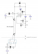
As I mention, the "source" circuit has isolated DC supply and ground in respect to the opamp mixer. Its output impedance varies a bit due to the use of a coupling cap, but at 1kHz its about 21 Ohm (goes to about 150 Ohm at low frequencies), so I omitted it for clarity. I drew only one coaxial too for simplicity - remember, there are 10 of them in varying lengths (roughly 21, 20, 17.9, 15.8, 13.7, 11.6, 9.5, 7.4, 5.3, 3.2 cm in "body" length).
When the switches are in the position shown (bypass), I get that hum from these 10 coaxials hanging in the air and going into the inverting input. When the switches change their position to include the source signal, the hum stops, practically regardless of the setting of the 50k potentiometer. Setting it to 100% may have a tiny bit of noise more than setting it to 0%, but I haven't managed to distinguish it for sure, and it is clear that it comes from the source, if it exists.
My initial thought due to this experiment was to terminate the hanging coaxial end with a 10k/2,2uF series network, to mimic the effect of the termination used in the engaged "source" position with a pot setting of 0%. I tried it for the longest coaxial but did not work as I initially hoped. Maybe tuned the hum a bit down, but not as effectively as when the "source" is engaged. Maybe I soldered them hastily (for sure I did not care to cut the parts' legs so they were hanging outside the board). Should such a treatment work? Or maybe trying another termination?
(Disclaimer: I can't use any part of the "source" circuit in bypass mode because this would create a ground loop)
Attachments
What happens when you only keep the grounds connected? (I don't understand your disclaimer; why would there be a loop when they are isolated domains?)
What happens when you only keep the grounds connected? (I don't understand your disclaimer; why would there be a loop when they are isolated domains?)
Yes, I must explain it, sorry for the misunderstanding.
When the switches are in bypass mode, the "source" circuitry is (or could) be used as part of the "input" circuit. Thus, if I connect the shield to the source ground, I would create a ground loop since the shield would be already connected to it via the NE5532 ground.
So I haven't tried it as a solution..
Could you try it as an experiment?
Yes, I will, this is easy to test for one coaxial.
If it doesn't work, should I try using a shielded twisted pair to carry the NE5532 to the switch end via its shield, in order to ground the "return" conductor of the pair at the source end in bypass?
One other thing you could try is putting 100 ohm between the source and summation circuit grounds. That will much reduce the current that can flow through a ground loop and still ensure that the source domain doesn't float completely with respect to the summation circuit.
What I'm wondering about is if due to primary to secondary capacitance in supply transformers there could be 115 V or 230 V RMS AC between the domains when the switches are off. The slightest capacitance from the switched-off domain into the centre conductor of the coaxial cable could then cause hum. Keeping some weak connection between the grounds of the domains should solve that.
What I'm wondering about is if due to primary to secondary capacitance in supply transformers there could be 115 V or 230 V RMS AC between the domains when the switches are off. The slightest capacitance from the switched-off domain into the centre conductor of the coaxial cable could then cause hum. Keeping some weak connection between the grounds of the domains should solve that.
Could you try it as an experiment?
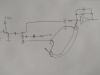
Well I just tried it, and it seems to be working!!
How could this be actually explained? I assume that the ground loop formed does not deteriorate my signal (at least audibly) because I was careful to minimize the pcb trace lengths, and so since the inverting input is at same potential as ground the "pollution" from the loop should be larger in order to be audible.
Of course, my knowledge can have a gap that I would gratefully fill! 🙂
I also attach a hand sketch of the loop I formed in practice but does not seem to matter.
To translate your proposition about the ground resistor, should I make this bypass connection using a 100 Ohm resistor? That means, connecting the shield at the source end to source ground via a 100 Ohm and not directly, as I did now.
I will try it now of course, but I am curious if this would help things.
EDIT: I tried the connection via the 100 Ohm, and did not hear any difference.
Attachments
Last edited:
- Home
- Design & Build
- Construction Tips
- Coaxial noise pickup