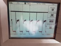
Is your scope actually set to 5v/div (probe on 10x when the scope thinks it's 1x)?
Scope is actually set to 500mv/div and probe and scope on 10x
Many scopes with a display have the ability to display the values correctly by being told whether the probe is 1x or 10x.
If this is 5v/div, I think the spike should be clamped by the base/emitter junction of the PS transistors. Are you sure that the transistors on that side of the amp are OK?
If this is 5v/div, I think the spike should be clamped by the base/emitter junction of the PS transistors. Are you sure that the transistors on that side of the amp are OK?
Many scopes with a display have the ability to display the values correctly by being told whether the probe is 1x or 10x.
If this is 5v/div, I think the spike should be clamped by the base/emitter junction of the PS transistors. Are you sure that the transistors on that side of the amp are OK?
I know, i have checked with probe comp and the probe scale is correct. Vpp of this wave is 500mv.
I don't sure that this transistor is ok, but i have this situation on both sides
Set the probe to 1x and repost the image.
I have to change volts scale
Attachments
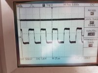
Set the scope to DC coupling?
This is situation with DC setting
Attachments

Working with car audio, it's almost never good to have the scope on AC coupling and in most cases, it makes the waveforms absolutely useless. When I was working, I probably only set my scope to AC coupling a few times a year. It's like having a meter set to AC volts when you're trying to read DC voltage. Everyone reading this should understand this if they're using a scope. Leave your scope on DC coupling, unless you have a VERY good reason to go to AC coupling.
Look at the drive from another amp using BJTs (below). As you can see, it's similar to the images you posted on AC coupling but it's actually completely different.
Now that you've switched to DC coupling and made it clear about the probe setting, your waveform makes more sense but I cannot say definitively that it's right. As was stated before, this drive circuit was rare. I think everything is OK. The 0.7v of drive above ground (without base resistors) is what I'd expect.
Unless someone knows this circuit, you'll have to draw the circuit from the output of the 494 all of the way to the bases of the 6488s to know more definitively if the drive is right.
ok, but i don't have 6488 but BD911 on power supply (this amplifier was repaired not from me in the past).
could be the problem?
could be the problem?
The 911s are a bit slower than the 6488s. They may be OK but I've never tried them in this application.
What do you consider to be a problem at this point?
What do you consider to be a problem at this point?
now, with 33ohm resistor, the noise on the power supply toroidal is stopped, but i have a little bump on the right channel, when power on and power off..The 911s are a bit slower than the 6488s. They may be OK but I've never tried them in this application.
What do you consider to be a problem at this point?
Are you saying that there is a turn on/off pop in the right channel?
That's in the muting circuit. Drive a signal into the amp. Does the left channel mute normally?
Is there any DC voltage on the right channel when the amp is in operation?
That's in the muting circuit. Drive a signal into the amp. Does the left channel mute normally?
Is there any DC voltage on the right channel when the amp is in operation?
yes, only on the right channelAre you saying that there is a turn on/off pop in the right channel?
yes, without popThat's in the muting circuit. Drive a signal into the amp. Does the left channel mute normally?
i will check and let you knowIs there any DC voltage on the right channel when the amp is in operation?
I have checked.
On the good channel, i have first 0,02V, after 2-3 sec goto 0,002V.
On the "bad" channel, i have 0,02v and don't change
On the good channel, i have first 0,02V, after 2-3 sec goto 0,002V.
On the "bad" channel, i have 0,02v and don't change
Do both channels drive a load to clipping, symmetrically?
How bad is the pop? Very slightly audible or so loud that it's likely to blow the cone out of the speaker frame?
How bad is the pop? Very slightly audible or so loud that it's likely to blow the cone out of the speaker frame?
Yes, symmetricallyDo both channels drive a load to clipping, symmetrically?
How bad is the pop? Very slightly audible or so loud that it's likely to blow the cone out of the speaker frame?
Is very audible, not blow the cone out of the speaker frame but middle level... is bigger when power on than power off
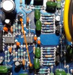
Short the muting transistor from leg 1-2. Does that stop the popping?
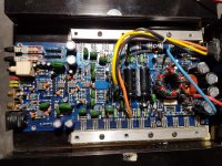
Can you tell me location about muting transistors? Picture in attached
Attachments
- Home
- General Interest
- Car Audio
- Orion 250sx with BJT on power supply