I edited there because I paused to double check your piezo crossover before proceeding further.
The positive input terminal connects to the resistor which connects to the capacitor which connects to the piezo i.e. all three are in series. Correct me if I'm wrong!
Given that is the case, my fix would be to solder a resistor directly across the terminals of the piezo i.e. in parallel with the piezo. This is in addition to the existing components.
We need a ceramic (wirewound) resistor of resistance no less than 22 ohm and of a decent power handling capacity. Looking around, this particular resistor and source may be the most accessible to you: 22 Ohm 20 Watt 5% Ceramic Wirewound Resistor - Willys-Hifi Ltd
While you are ordering, you may like to consider upgrading the capacitor with this more reliable type: Monacor 4.7uf 250V 5% Bipolar MKT Polyester Capacitor - Willys-Hifi Ltd
Attachments

Last edited:
Piezzo sound is rubbish. I would invest in an compression horn, but You need at least a 12dB crossover.
Piezos do differ between brands. Even seemingly identical piezos from the same brand can sound completely different. Unfortunately, there is no way to tell what one to buy, as they all look similar (they are copies of Motorola piezos). Real CTS or Motorola piezos are said to be better, but are expensive at $20+ each.
Assuming your piezo failed because the metal disk detached from the paper cone, you can repair it by glueing it back in place. It can detach when the disk gets too hot and melts the glue.
Usually, the remainder of the speaker is not worth upgrading to a compression driver and crossover. If you do not like the piezo, try Galu's suggestion or sell the speakers and buy something else.
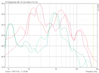
For those who are interested, attached are quick and dirty frequency response measurements of 8 cm diameter piezos (green) and 12 cm diameter piezos with integrated transformer and 3.3 µF capacitor (red). Within this test, the 12 cm piezo is much better. The drop off > 10 kHz probably is due to my setup.
Assuming your piezo failed because the metal disk detached from the paper cone, you can repair it by glueing it back in place. It can detach when the disk gets too hot and melts the glue.
Usually, the remainder of the speaker is not worth upgrading to a compression driver and crossover. If you do not like the piezo, try Galu's suggestion or sell the speakers and buy something else.
For those who are interested, attached are quick and dirty frequency response measurements of 8 cm diameter piezos (green) and 12 cm diameter piezos with integrated transformer and 3.3 µF capacitor (red). Within this test, the 12 cm piezo is much better. The drop off > 10 kHz probably is due to my setup.
Attachments
Last edited:
Ok so now have the piezo replacement, thanks TBTL for the recommendations, will keep the broken one and glue it back as a back up.
Just want to check for sure before I solder, have I got the positive and negative wires right?? on the last tweeter there were no signs but the new one has a positive and negative side so just making sure I know for sure which wire is which.
Just want to check for sure before I solder, have I got the positive and negative wires right?? on the last tweeter there were no signs but the new one has a positive and negative side so just making sure I know for sure which wire is which.
Attachments
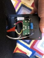
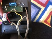
Yes, the capacitor should go to the positive terminal on the piezo.Just want to check for sure before I solder, have I got the positive and negative wires right??
- Home
- Live Sound
- PA Systems
- Blown Tweeter replacement with unknown crossover