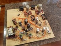
Hello everybody, please take a look at a prototype GU-50 amp ive built.
Can you tell us a bit more about it and how does it sound?
Btw, I’m in Mesa.
Cheers,
GREG
A schematic would be nice indeed.
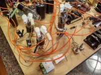
I get the impression that the filament of each GU50 is being fed from a 6.3 Vac tap on the power transformer, which gets rectifed by a bridge rectifier and than smoothened by an electrolytic capacitor. The GU50 needs 12.6 V for the filament. With 6.3 Vac to begin with, you will not even come close to 12.6 Vdc (more something like 8 V). Or do the black parts contain more than just a bridge rectifier? If there are indeed two 6.3 Vac taps on your power transformer, you could connect them in series to get the required 12.6 V for the GU50's
I get the impression that the filament of each GU50 is being fed from a 6.3 Vac tap on the power transformer, which gets rectifed by a bridge rectifier and than smoothened by an electrolytic capacitor. The GU50 needs 12.6 V for the filament. With 6.3 Vac to begin with, you will not even come close to 12.6 Vdc (more something like 8 V). Or do the black parts contain more than just a bridge rectifier? If there are indeed two 6.3 Vac taps on your power transformer, you could connect them in series to get the required 12.6 V for the GU50's
The building style of TS looks a bit like the style of forum member brightcity to me.
Last edited:
The building style of TS looks a bit like the style of forum member brightcity to me.
Looks more like coolcity to me 😉
"Hello everybody, please take a look at a prototype GU-50 amp ive built" and......?
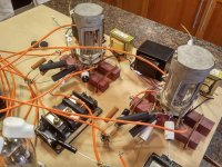
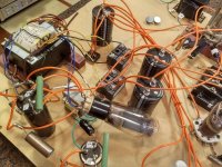
Apart from the spanky valve holders for the GU50's and your use of 2C34/DET32's? not much to comment on, apart from your OPT's look a bit on the small side.
Andy.
Apart from the spanky valve holders for the GU50's and your use of 2C34/DET32's? not much to comment on, apart from your OPT's look a bit on the small side.
Andy.
I guess the tube sockets depicted are the best ones that you can get these days. They surely are NOS, of Russian or Sovjet origin, and they hold the tube in one (!) certain position.Apart from the spanky valve holders for the GU50's...
You'll have to remove that black plastic knob from the tube's top, otherwise the lid can't be closed, and take care not to lose it. Otherwise replacing a worn out tube might get somewhat tricky 😉.
Best regards!
Last edited:
Those are some AliExpress specials.Apart from the spanky valve holders for the GU50's and your use of 2C34/DET32's? not much to comment on, apart from your OPT's look a bit on the small side.
- Home
- Amplifiers
- Tubes / Valves
- GU-50 Amp