I have a combo of output transformers from Philips Jupiter 404 stereo radio.
I'm not sure if/how they may be used for EL84 SE amp. The connection in the radio is a bit unusual (to me). Could somone explain the output stage of the radio and how these transofmers can be used to build EL84 SE amp?
Thanks!
I'm not sure if/how they may be used for EL84 SE amp. The connection in the radio is a bit unusual (to me). Could somone explain the output stage of the radio and how these transofmers can be used to build EL84 SE amp?
Thanks!
Attachments
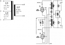
The part of the primary between taps 1 and 2 is an 'anti-hum' provision, and sometimes also contributes a little in preventing core saturating. Philips (and other brands) used this often in their radio's.
The part of the primary between taps 2 and 3 is the 'normal' part of the primary. You can connect your filtered B+ to tap 2, and the anode of the EL84 to tap 3 (like in your schematic).
From tap 1 you can take B+ for the preamplifier stage(s). I think a small resistor (like the one of 1K8 in your schematic) is a good idea so to get some more decoupling between stages. Install an electrolytic capacitor to ground after this resistor.
In your schematic, the two leads from the taps 1 are joined after the resistors, but if you build an audio amplifier with them, you don't have to let them join again. Just use one for each channel.
The winding ratio is 3000:80 (= 37.5) so the impedance ratio is 1406:1 (= 37.5 squared). The loudspeakers in this radio are 5 Ohm, so the primary impedance is about 7031 Ohm (5 x 1406). That value corresponds with the voltages, currents and the common cathode bias resistor (110 Ohm) in your schematic, if compared to the Philips datasheet for the EL84.
....how these transofmers can be used to build EL84 SE amp?
It IS an EL84 amp. Just copy it. With modern caps, in DIY context, I would not use the pin 1 taps but just filter the low-level B+ adequately.
Leaving out S36 the LF response will distort at levels over 1W. This trick makes use of an opposed DC current (20mA probably) to overcome core saturation. In AC terms it is loading the final as well, but I am not shure how the rest of the circuit is connected.
Last edited:
Leaving out S36 the LF response will distort at levels over 1W. This trick makes use of an opposed DC current (20mA probably) to overcome core saturation. In AC terms it is loading the final as well, but I am not shure how the rest of the circuit is connected.
Winding S35, 3,000 turns, 32ma, 96 amp-turns.
Winding S36, 165 turns, (say) 20ma, 3.3 amp-turns.
96AT:92.7AT, less than 4% difference, less than a semi-tone in frequency.
Loading: the 1.8k is reflected as (3000/165)^2 or 331 times higher, 595 kOhms, 70 or 100 times higher than the reflected speaker load.
Yes, of course, it works either way. The goal from RCA's patent is to reduce filtering costs (ripple cancellation). This requires empirical tests. The 3000:165 ratio will not be correct if you change ANYthing in the rest of the amp. The 4% difference in flux is trivial. And the whole idea confuses people.
The 3000:165 ratio needs to be almost equivalent to the quotient of the tube's plate resistance and 1.8 kohms for best hum cancellation. It's a bridge w.r.t the hum current.
To the other aspects of the circuitry: As only the finals are shown, I guess that one of both is driven by an inverted phase signal. Hence, as seen from the bass speaker, both work in BTL, while the tweeters are connected in antiphase.
Best regards!
To the other aspects of the circuitry: As only the finals are shown, I guess that one of both is driven by an inverted phase signal. Hence, as seen from the bass speaker, both work in BTL, while the tweeters are connected in antiphase.
Best regards!
The schematic can befound here: Jupiter 404 Stereo B4D04A dunkles Gehause Radio Philips Radi
The channels seem to be in phase with each other.
The channels seem to be in phase with each other.
One of the speaker connections of the OPT's is inverted.The channels seem to be in phase with each other.
Mona
OK, if both Kay and you say so, than probably they are not in phase. Do you know this radio (I don't) and/or can you deduce this from the schematic (I can't)?
Addition: Wouldn't the bass be partly canceled if the two speakers are driven in anti-phase with each other?
Addition: Wouldn't the bass be partly canceled if the two speakers are driven in anti-phase with each other?
Last edited:
In it's normal situation (no external speakers connected, both ground switches closed) both onboard speakers indeed are driven in antiphase, but I guess they're also connected invertedly, hence operate as usual. If two external speaker are attached, the ground switches are open and the internal speakers are connected via inductor S49, hence operating as bass speakers, or via the closed switch 17-18, then operating with full bandwidth.
Best regards!
Best regards!
My findings come from decades ago when experimenting with this sort of OT. I ran the plate from the junction while the screen was connected to the bottom. On loud bass notes the output distorted and sometimes the OT produced a noise like in a short circuit. No sparks observed though.Yes, of course, it works either way. The goal from RCA's patent is to reduce filtering costs (ripple cancellation). This requires empirical tests. The 3000:165 ratio will not be correct if you change ANYthing in the rest of the amp. The 4% difference in flux is trivial. And the whole idea confuses people.
If you supplied the screen grid this way without any filtering, you added PFB. Hence, no wonder about your experiences.
Best regards!
Best regards!
One of the speaker connections of the OPT's is inverted.
Mona
So the speaker connections of one of the two the OPT's is inverted, but according to Kay one of the two speakers is also connected inverted. So with no external speaker(s) connected (so with only the two speakers inside the radio itself, one for each channel), it still looks to me that the two channels are in phase...
Yes, that should read "G2" 😉If you supplied the screen grid this way without any filtering, you added PFB. Hence, no wonder about your experiences.
Best regards!
You are right, no phase inversion here.So the speaker connections of one of the two the OPT's is inverted, but according to Kay one of the two speakers is also connected inverted. So with no external speaker(s) connected (so with only the two speakers inside the radio itself, one for each channel), it still looks to me that the two channels are in phase...
It looks like it, one output ground on top the other ground at the bottom, but the whole transformer is upside-down.
There is no stereo source inside but still a mono/stereo switch.
Perhaps the swith at the speaker is part of the mono/stereo switch and it is the responsebility of the outside source to invert one side.
Mona
- Home
- Amplifiers
- Tubes / Valves
- How to use Philips Jupiter 404 output transformers?