Hi,
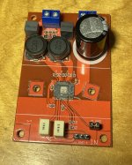
I bought a couple of the Chinese red mono TPA3116 boards on eBay, that have balanced inputs. I have connected them to a professional line level source (+4dBu) and they have far too much gain.
I started investigating what the gain value was set to on the boards and have been a bit confused by the resistor values:
R1 = 01D = 100kΩ (SDZ to PVCC?)
R2 = 473 = 47kΩ (GVDD -> GAIN - aka R2 on data sheet)
R3 = 01D = 100kΩ (GAIN -> GND - aka R1 on data sheet)
These are valid combinations listed on the datasheet, and it doesn't seem to match any of them?
Closest appears to be Slave / 32 dB. But I would presume that it wouldn't work at all in save mode without a master.
Am I reading these resistors wrong?
Or have they chosen weird values?
Does anyone else have one of these boards and changed the gain on them?
Apart from the high-gain, the board is working well and appears to be sensible.
Really not excited about replacing tiny SMD resistors! 🙁
Thanks!
njh.
I bought a couple of the Chinese red mono TPA3116 boards on eBay, that have balanced inputs. I have connected them to a professional line level source (+4dBu) and they have far too much gain.
I started investigating what the gain value was set to on the boards and have been a bit confused by the resistor values:
R1 = 01D = 100kΩ (SDZ to PVCC?)
R2 = 473 = 47kΩ (GVDD -> GAIN - aka R2 on data sheet)
R3 = 01D = 100kΩ (GAIN -> GND - aka R1 on data sheet)
These are valid combinations listed on the datasheet, and it doesn't seem to match any of them?
Code:
MODE     GAIN     R1 (to GND)   R2 (to GVDD)
Master   20 dB    5.6 kΩ        OPEN
Master   26 dB    20 kΩ         100 kΩ
Master   32 dB    39 kΩ         100 kΩ
Master   36 dB    47 kΩ         75 kΩ
Slave    20 dB    51 kΩ         51 kΩ
Slave    26 dB    75 kΩ         47 kΩ
Slave    32 dB    100 kΩ        39 kΩ
Slave    36 dB    100 kΩ        16 kΩ
Closest appears to be Slave / 32 dB. But I would presume that it wouldn't work at all in save mode without a master.
Am I reading these resistors wrong?
Or have they chosen weird values?
Does anyone else have one of these boards and changed the gain on them?
Apart from the high-gain, the board is working well and appears to be sensible.
Really not excited about replacing tiny SMD resistors! 🙁
Thanks!
njh.
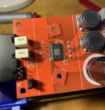
Attachments
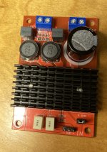
That thermal paste all over the pins is conductive, made of aluminium or silver particles, you need to clean that up thoroughly to avoid future shorting disaster...
Add external 51k in series on each input. You get gain 20db.
That is the best way, changing feedback resistor can upset stability.
Hi,
I bought a couple of the Chinese red mono TPA3116 boards on eBay, that have balanced inputs. I have connected them to a professional line level source (+4dBu) and they have far too much gain.
I started investigating what the gain value was set to on the boards and have been a bit confused by the resistor values:
R1 = 01D = 100kΩ (SDZ to PVCC?)
R2 = 473 = 47kΩ (GVDD -> GAIN - aka R2 on data sheet)
R3 = 01D = 100kΩ (GAIN -> GND - aka R1 on data sheet)
These are valid combinations listed on the datasheet, and it doesn't seem to match any of them?
Closest appears to be Slave / 32 dB. But I would presume that it wouldn't work at all in save mode without a master.Code:MODE GAIN R1 (to GND) R2 (to GVDD) Master 20 dB 5.6 kΩ OPEN Master 26 dB 20 kΩ 100 kΩ Master 32 dB 39 kΩ 100 kΩ Master 36 dB 47 kΩ 75 kΩ Slave 20 dB 51 kΩ 51 kΩ Slave 26 dB 75 kΩ 47 kΩ Slave 32 dB 100 kΩ 39 kΩ Slave 36 dB 100 kΩ 16 kΩ
Am I reading these resistors wrong?
Or have they chosen weird values?
Does anyone else have one of these boards and changed the gain on them?
Apart from the high-gain, the board is working well and appears to be sensible.
Really not excited about replacing tiny SMD resistors! 🙁
Thanks!
njh.
Hi njh,
You may be in the same situation as I with the red board:
TPA3116 D2 mono amplifier as a stereo system? , posting #57. If so, you may need to heat-up the soldering iron.
FF
Pins 13-16, the last four on right are grounded. You can liberate the pin 13 by a scalpel to join it +V by 100k resistor. Your amp than runs at 1.2 Mhz.
Thanks for all the replies! Really useful things for me to look into.
What is the advantage of running it at 1.2 Mhz?
I thought that changing the frequency was for AM frequency avoidance?
Aha! Thanks FauxFrench!
Really good to see that someone else had found the same thing and that I'm not reading the circuit / resistor values wrong. Hm, I have not soldered/desoldered anything that small before 🙁
Kind of rubbish that 2 years later they are still making/selling boards with the same fault.
I have not experienced the chokes heating up but I don't think I have run it solidly for an hour. I should read that thread properly and see if there is anything else relevant in it.
It isn't actually a feedback resistor. It is a potential divider that puts a voltage into an ADC in the chip as a way of configuring it.
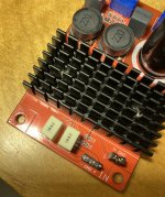
Thanks! I will give it a clean. I am fairly sure it must have been like that when I bought it 🙁
Even if I manage to re-configure the gain of the amplifier, I think I am also going to reduce the input signal.
Is 51k is fairly standard value to use for converting from +4dBV to -10dBU?
Is putting the resistor in series, better than using a potential divider?
Pins 13-16, the last four on right are grounded. You can liberate the pin 13 by a scalpel to join it +V by 100k resistor. Your amp than runs at 1.2 Mhz.
What is the advantage of running it at 1.2 Mhz?
I thought that changing the frequency was for AM frequency avoidance?
Hi njh,
You may be in the same situation as I with the red board:
TPA3116 D2 mono amplifier as a stereo system? , posting #57. If so, you may need to heat-up the soldering iron.
FF
Aha! Thanks FauxFrench!
Really good to see that someone else had found the same thing and that I'm not reading the circuit / resistor values wrong. Hm, I have not soldered/desoldered anything that small before 🙁
Kind of rubbish that 2 years later they are still making/selling boards with the same fault.
I have not experienced the chokes heating up but I don't think I have run it solidly for an hour. I should read that thread properly and see if there is anything else relevant in it.
That is the best way, changing feedback resistor can upset stability.
It isn't actually a feedback resistor. It is a potential divider that puts a voltage into an ADC in the chip as a way of configuring it.
That thermal paste all over the pins is conductive, made of aluminium or silver particles, you need to clean that up thoroughly to avoid future shorting disaster...
Thanks! I will give it a clean. I am fairly sure it must have been like that when I bought it 🙁
Add external 51k in series on each input. You get gain 20db.
Even if I manage to re-configure the gain of the amplifier, I think I am also going to reduce the input signal.
Is 51k is fairly standard value to use for converting from +4dBV to -10dBU?
Is putting the resistor in series, better than using a potential divider?
Pragmatic demonstration is far better way to explain than theory.
Listen to this music Put Your Records On - Bossa Nova Hits 2015 - Fullsong - YouTube with original mode. You will hear very dirty sound. If you doubt MP3 you have the same in wave streaming Shazam
Now add series resistors of 51k, 100k and 220k and notice how the sound gets better and better. Switching to 1.2Mhz it sounds still far better to be in match with SET 300b, see Sublimed TPA3116D2.
The AM radios near by the amp or speakers will capture the stations at 1200khz with parasite, if you or your neighbors are still using AM radios it might be a problem. According to FCC rules commercializing such product is against the rules.
Last edited:
Thanks for suggesting something to listen to/test with kokoriantz.
I think I am going to try and get this build finished and usable but may go back to trying to adjust the frequency later. Soldering on to those tiny leads is hard and would rather fix my more substantial problems first.
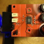
I think have successfully managed to reduce the gain to 20dB, as FauxFrench described in the other thread.
Removing R2 was pretty easy. I used a largish soldering tip with a blob of solder and was able to heat both sides of the resistor R2 at the same time, so it floated straight off very easily.
I used a (sewing) pin to bend up the SYNC pin, while heating the pad with the soldering iron - again not very hard. I actually ended up snapping the pin off, semi-deliberately to avoid it re-connecting to ground again.
So very glad I didn't have to replace a SMD resistor...
With the reduced gain, the hiss (full volume, nothing playing) is almost inaudible, so a worthwhile improvement, I think
But still far too much gain with my +4dBV signal, so I am now looking at using U-pad attenuator.
This webpage describes building a U-pad really well:
Uneeda Audio - Build your own attenuator pads
Seems a bit will putting an attenuator, in front of an amplifier - but I think that is what is required.
I think I am going to try and get this build finished and usable but may go back to trying to adjust the frequency later. Soldering on to those tiny leads is hard and would rather fix my more substantial problems first.
I think have successfully managed to reduce the gain to 20dB, as FauxFrench described in the other thread.
- I removed R2 completely - living it in the 'Open' state
- This leaves the 100kΩ resistor (aka R1) pulling GAIN to ground. This is much higher than the recommended 5.6k but seems to be fine.
- I successfully lifted the SYNC pin, so it is no-longer connected to ground. Hopefully avoiding the overheating issue that FauxFrench experienced.
Removing R2 was pretty easy. I used a largish soldering tip with a blob of solder and was able to heat both sides of the resistor R2 at the same time, so it floated straight off very easily.
I used a (sewing) pin to bend up the SYNC pin, while heating the pad with the soldering iron - again not very hard. I actually ended up snapping the pin off, semi-deliberately to avoid it re-connecting to ground again.
So very glad I didn't have to replace a SMD resistor...
With the reduced gain, the hiss (full volume, nothing playing) is almost inaudible, so a worthwhile improvement, I think
But still far too much gain with my +4dBV signal, so I am now looking at using U-pad attenuator.
This webpage describes building a U-pad really well:
Uneeda Audio - Build your own attenuator pads
Seems a bit will putting an attenuator, in front of an amplifier - but I think that is what is required.
Attachments
- Home
- Amplifiers
- Class D
- Reducing gain on red mono TPA3116 board?