Hi Folks,
Great to be here, and this is my first post!
My company Pangolin manufactures laser equipment, including servo drivers and laser scanners.
We use LM3886 as a part of our servo driver. Our servo driver is like an audio amplifier, and our scanner (motor) is like a speaker. Our laser scanners have impedance properties similar to a speaker, so the LM3886 works well for this application.
The LM3886 is incorporated into a digital servo driver. This servo driver has a multi-channel A/D, and with a high sample rate, we digitize both the voltage coming from the LM3886 output, and also the current flowing through the scanner's coil (current that is ultimately provided by the transistors in the LM3886).
Digitizing the voltage and current provides great insight towards our servo system operation. I can graph these over time, and create oscilloscope waveforms of various quantities, including this voltage and current. We can also perform "math" on these, and graph related quantities.
For example, we calculate the average power dissipated (heat generated) by our scanner (like the speaker in an audio system). To accomplish this, we simply do RMS Current squared, multiplied by the coil resistance. (One way to get Average Power is I^2R.) Since we digitize the current, it's easy to do an RMS computation on the samples and obtain that quantity.
We'd also like to calculate the actual power dissipation (i.e. heat generated) on the part of the LM3886. In other words, I'd like to calculate the average power. But for the power amplifier, I'm having trouble wrapping my head around how to do that. It seems a bit more tricky.
The question is about calculating power dissipation (watts) in real time based on data samples.
-------------------------------------------
As I mentioned, our servo driver has digitizes both the voltage that is output from the power transistors to the motor coil (we call this "Instantaneous voltage") and also the current flowing through the motor's coil (we call this "Instantaneous current"). We sample these quantities very often, so at all times the servo driver is aware of the instantaneous voltage and current.
I'd like to calculate the heat generated by the power transistors while they are supplying current to the coil.
Presently my way of calculating this is shown below.
if(InstantaneousCurrent >= 0)
{ //Current is positive -- must be coming from the positive transistor
InstantaneousTransistorVoltage = (PositiveRailVoltage - InstantaneousVoltage); //For example, 24 - 21 = 3V
InstantaneousTransistorPower = InstantaneousTransistorVoltage * InstantaneousCurrent; //For example: 3V * 3A = 9W (Power = Voltage * Current)
}
else
{ //Current is negative -- must be coming from the negative transistor
InstantaneousTransistorVoltage = (NegativeRailVoltage - InstantaneousVoltage); //In this case transistor voltage will be negative (-24V - -21V = -3V
InstantaneousTransistorPower = InstantaneousTransistorVoltage * InstantaneousCurrent; //For example: -3V * -3A = 9W (Power = Voltage * Current)
}
AverageTransistorPower += CurrentFilterConstant * (InstantaneousTransistorPower - AverageTransistorPower);
So, in other words, for each sample, I take the instantaneous voltage through either the upper transistor or lower transistor as applicable, and multiply it by the instantaneous current to obtain an "InstantaneousTransistorPower", and then average that over time.
Alternatively I could calculate the heat in the upper transistor if(InstantaneousCurrent >= 0), or heat in the lower transistor, and then sum the two together.
Either of these techniques make intuitive sense to me.
--------------------------
But then, just today, while searching for "calculating average power", I see "Average power = VRMS * IRMS". So, they're multiplying the RMS of each.
My code presented above above makes intuitive sense, but it deals only with the average. So it would be like "Average Power = Average Voltage * Average Current". For sure Average isn't the same as RMS.
So here's the question for all of you folks on DIY Audio: Should I be calculating the RMS voltage that appears across each transistors, and multiplying that by the RMS current flowing through each transistor (and then summing the upper and lower transistors)?
Note that sometimes the current flows through the positive transistors, and sometimes through the negative transistor. In the case of the LM3886, both are in the same physical package so I don't care too much, and it's all about the heat that is being generated, and thus must be dissipated by the user.
---------------------------
Best regards,
William Benner
Many years ago, a couple of errant Yamaha Electronics boffins developed a servo amplifier for exactly the purpose you describe, to drive servo stepper motors.
It was an FM class D amplifier that was so successful developed into the Flying Mole HiFi Amplifier.
In that sort of circumstance, there is less than 4% dissipation in the switching transistors and Mos output pairs were selected with a mere 12W dissipation but a massive 32A switching capability.
These modules switched a 22A load at 48volts. If it were a linear stage the dissipation would be quite substantial but being digital, 0 or 1; off or on, then the dissipation was low enough to only require a moderate heat sink. Earlier drivers were class A with fan assisted cooling!
Average power is difficult to calculate but easy to measure.
My maths totally fails me on this I'm afraid but it is an interesting question.
So... I guess one aspect is whether you are talking about signals that are sine in nature or whether they are asymmetric. The average of a sine is zero... so should we be using rms quantities.
If we look at the currents and voltages involved in a typical chip amp like the LM3886 we might get a clue.
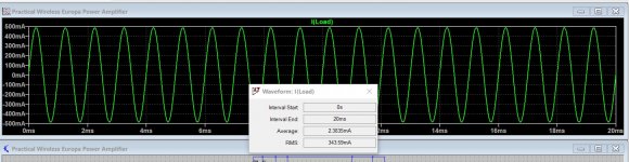
This shows a typical output stage (just like an LM3886) delivering approximately -/+500ma into an 8 ohm load.
The average load current is zero (its a sine) but the rms current here is shown as 343ma. Image 1.
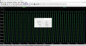
If we look at each transistor current we see this. The current in each transistor is traced out and the detail for one of them is shown. Image 2.
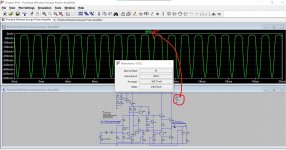
The power supply is 56 volts DC (single rail). We can look at the overall current draw from this supply. Image 3.
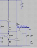
I don't know if that helps or not but you might be able to piece the maths together from a visualisation of the currents. The final image shows the output stage diagram being measured.
So... I guess one aspect is whether you are talking about signals that are sine in nature or whether they are asymmetric. The average of a sine is zero... so should we be using rms quantities.
If we look at the currents and voltages involved in a typical chip amp like the LM3886 we might get a clue.
This shows a typical output stage (just like an LM3886) delivering approximately -/+500ma into an 8 ohm load.
The average load current is zero (its a sine) but the rms current here is shown as 343ma. Image 1.
If we look at each transistor current we see this. The current in each transistor is traced out and the detail for one of them is shown. Image 2.
The power supply is 56 volts DC (single rail). We can look at the overall current draw from this supply. Image 3.
I don't know if that helps or not but you might be able to piece the maths together from a visualisation of the currents. The final image shows the output stage diagram being measured.
Attachments
Do you have a plot of the phase angle of the load at various frequencies? Curious to see if it also looks like a loudspeaker's impedance plot.
If the load's well behaved (similar to a resistor) then the current through each output transistor is always going to be in one direction, as is the voltage. Then there's no need to go to the additional complication of calculating the RMS voltage and current across/through each transistor. The example code you've given would then look to me to be the way to go. If the power supply to the LM3886 is tightly regulated then maybe you won't need to measure the rails with an ADC channel, rather assume they're at their regulated values.
If the load's well behaved (similar to a resistor) then the current through each output transistor is always going to be in one direction, as is the voltage. Then there's no need to go to the additional complication of calculating the RMS voltage and current across/through each transistor. The example code you've given would then look to me to be the way to go. If the power supply to the LM3886 is tightly regulated then maybe you won't need to measure the rails with an ADC channel, rather assume they're at their regulated values.
Hi everyone,
Thanks for the feedback so far. The power supply is well regulated normally, but we digitize it anyway, albeit at not a very high sample rate.
So we know the power supply for both + and -, and at any instant we know the voltage coming from the power transistors (and thus the drop across each transistor) and we also know the current flowing through each transistor. We know this at a very high digitizing rate of > 100kSPS.
I guess you'll have to trust me that the load is pretty much like a speaker. Mostly resistive, with a little bit of inductance.
Regarding the comment about PWM amplifiers, yes, we have some of those too, including one that can drive 32 amps into 1 ohm at 50 volts. But it's bigger, more complicated, etc. For most of our clients, the LM3886 offers enough performance, and it's cheap and simple. Overall the system doesn't run unreasonably hot. It's just that we've got this scope function as a part of our software, and I'd like to report -- to the user -- the average power of both the load (speaker or small motor) and also the average power (i.e. heat generated) by the power amp.
Bill
There's no practical ambiguity RMS or average; Dissipation is a DC quantity.
And math aside (if Mooly hesitates, I won't even try), you can measure it with a thermometer. How hot is the heatsink? How much DC has to flow to hit the same hot?
Yes, multiplying transistor voltage times transistor current, point by point, and taking a running average, should give the right answer.
The Idiot is good at mindless math like this. It is tedious to set-up and to *verify* you are asking the question right, but it chews bits quick. Here's a basic push-pull output (always minimize). Probes read device V and I. "Negative power" is a math artifact so invert that (or use ABS). Sum the two devices. In my SPICE, RMS averages a few cycles. It shows that dissipation is a bit lower clipped-out than at half max, a known result for class B sine amps.
Attachments

So here's the question for all of you folks on DIY Audio: Should I be calculating the RMS voltage that appears across each transistors, and multiplying that by the RMS current flowing through each transistor (and then summing the upper and lower transistors)?
No, you need to calculate the real power as you are doing now. Average real power is the integral of instantaneous voltage x instantaneous current per unit time.
Only with a non-active, non-reactive load (ie a resistor), does multiplying the rms voltage and current work. The output transistors are active and may carry reactive currents (because the load is reactive).
Output transistors typically have the highest voltage across them when carrying least current and vice-versa, which is the complete opposite of a passive resistor.
The trick with multiplying rms voltage and current for a resistor works because its a pure resistance so current and voltage are proportional - any other situation the trick is wrong.
The product of rms voltage with rms current is termed "apparent power".
Last edited:
If you have simultaneous (high relative sample rate compared to waveform) access to both the voltage and current, you could multiply these to get the power in the load. If there's any phase shift between I and V, you'll get a funny looking power waveform - but I'd think mathematically you could run that through a software RMS converter which should give the real power - regardless of waveshape.
If you can do the same thing with the two +/- voltages going into the LM3886, you could assume the power supply voltages are fairly constant DC and work with the two current waveforms, possibly adding them together back to a sine-ish waveform - or invert one like you said. Run that waveform through the RMS converter, multiply that by the DC voltage value and you have your input power. Input - Output should then give you the power dissipation in the device.
Something like LabVIEW has an RMS conversion function that you input a sampled waveform to. I assume Python and everything else with math packages has this available to a test programmer as well. Hope this helps. Reply or PM me if the words arent clear - and I'd be glad to try again.
Last edited:
No, you need to calculate the real power as you are doing now. Average real power is the integral of instantaneous voltage x instantaneous current per unit time.
The product of rms voltage with rms current is termed "apparent power".
AHA this is very helpful and the way you put it, it makes perfect sense. I'm glad my intuition on this turned out to be correct.
"The way I do it now" (in code) is to calculate it as though there is a single element supplying the voltage. Sometimes that single element is the top transistor and sometimes it's the bottom transistor, and I multiply that by the current.
What I will try next is to separate this into power dissipated by the top and bottom transistors, and add those two quantities together and see if I come up with the same number.
Thanks everyone for the great feedback and lively discussion!
Best regards,
William Benner
In principle the instantaneous power dissipated by a transistor, whether it´s the PNP or NPN one is Instantaneous >>voltage drop across the transistor<< (so supply voltage minus instantaneous voltage across the load) times >>instantaneous<< current through it , times >>power factor<< because having an inductive load such as a servo means current and voltage won´t be in phase.
Then integrate that power along time, wouldn´t say across a cycle because we don´t have a continuous frequency wave (I guess) but along a certain time, say 1 second or longer.
I also guess (may be wrong) that you are ultimately worried/interested in die temperature for reliability reasons; you can make a device to measure the transistor (which is inside a chip and mounted on a heatsink) temperature after, say, a known pulse and calculate a thermal time constant.
Measuring is kludgy complicated, you might even have to drill the chipamp to install a thermocouple, but you do it *once*, on the bench, then your clever programmers can do the Math to estimate actual chip temperature with precision knowing the external factors.
Another safety factor: what happens if for any reason your scanner motor stalls? (which is entirely possible during operation).
You will lose back EMF and so it will pull more current and drop less voltage across its coils, and chipamp will dissipate and heat more.
The instantaneous power dissipated in the output stage is: P = (Vsupply-Vout)*Iout. Life gets more complicated with complex loads, but I suspect you could get a good number for the RMS power by using RMS measurements of Vsupply, Vout, and Iout.
Sedra/Smith, "Microelectronic Circuits" covers the math. I think they're up to the 8th edition now, but as with many textbooks the higher editions mostly exist to extract more money from students. The underlying physics haven't changed. Any of the older editions (at least back to the 3rd) would be just as valuable.
Tom
Last edited:
Measuring is kludgy complicated, you might even have to drill the chipamp to install a thermocouple, but you do it *once*, on the bench, then your clever programmers can do the Math to estimate actual chip temperature with precision knowing the external factors.
Also a kludge, but potentially easier to do: Attach a thermocouple on the metal tab of the LM3886T right below the mounting hole (or maybe even in a milled slot on the back side of the tab).
I don't know the precise location of the LM3886 die, but I would be surprised if it is not roughly centred left/right and roughly centred under the plastic part top/bottom. Of course, you can always cut one in half and find out... 🙂 I did that "a few" years back: See pictures and more pictures.
Tom
LM3886 (same with LM3875 and LM4780) not a happy camper at unity gain and all have been rendered obsolete by TI.
Trying to work out power into speaker and lost power into the heatsink depends a lot on signal levels.
You might have thought that on full voltage swing at the output yo uwould be losing most power in the heatsink but you aren't. On full swing the voltage is reaching the rails where little power is lost.
I did a PC program to track power lost in the heatsink and it turned out that worst case is when voltage is swinging to 2/3rd of the rails.
LM3886 (same with LM3875 and LM4780) not a happy camper at unity gain and all have been rendered obsolete by TI.
True that the LM3886 requires a closed loop gain of 10 V/V (20 dB) for stability unless you get fancy with the compensation. The LM3886 is still in active production, though. The other two (and LM3876) have been discontinued.
I did a PC program to track power lost in the heatsink and it turned out that worst case is when voltage is swinging to 2/3rd of the rails.
For sine wave signals, the worst case dissipation is when the amp dissipates half its rated power. That corresponds to Vout = Vsupply/sqrt(2), so 70% of the rails.
You can find the derivation in Sedra/Smith that I mentioned a few posts back.
Tom
The LM3886 is still in active production, though. The other two (and LM3876) have been discontinued.
My mistake, sorry. I thought that they had abandoned the entire series. (They also discontinued their driver chips LM4702, LME49830 etc.)
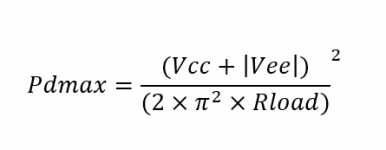
In the Nat Semi datasheets there were tables of PDmax vs Supply Rail voltages. TI in their infinite wisdom, has chosen to eliminate these, and also scrub the Excel spreadsheet which allowed one to calculate PDmax and thermal resistance of the heat sink.
Might want to check out Analog (LLTC) LT1166 chip which has current sense/limit if you need an analog driver. They have a "350W Shaker Table" ap in the data sheet.
Attachments
- Home
- Amplifiers
- Chip Amps
- Question about calculating power dissipation