I changed the trimpot, for a Bourns single turn, 100ohms guy, but the OEM one was ok, after i had cleaned it with Faderlube. I tried a few paralell resistors of different values in the trimpot's circuit, no change. The trimpot has a 33ohms resistor, parallel to it. I had to change that resistor to a 18ohms on the Left channel, to be able to achieve the 18MV required, as it was over-biasing even with trimpot all the way.
My problem is on the Right channel. The bias thermal diode, a STV-4H, seems ok as it measures the same as Left channel's.
The bias stays close to 0 to 1MV, even when warm. The driver's heat sink stays cooler then the right channel. Have no scope and, can't hear any crossover distorsion but?...Kenwood KA-801 High Speed DC Integrated Amplifier Manual | HiFi Engine
Amplifier looks bone stock and is freshly re-capped but the problem was there before. Checked Resistors; R-2, 4, 6, 10, and 16, all ok. Diodes; 2, 4, and 6 ok too. What do you guys think?
Have you checked what range of bias control voltage is available? This is measured between those two 27 ohms. You need enough to overcome four B-E junctions which typically means around 2.4 volts or more.
Older semiconductors seem to be fabricated using slightly different processes to modern parts and it is not unknown for the bias to be out of range if parts have been replaced due to slightly differing B-E forward voltages or modern parts. Worth checking all output and drivers are originals.
Duncan will know where this is leading... the STV4H will be four diodes in series giving about the 2.4 volts needed. The series trimmer just allows that value to go a little higher as measured between the base of the driver transistors.
Do you see the same voltage across each of those STV's
It would also be prudent to check the current flowing in the preset and STV chain. If that is low then the generated bias voltage would probably be low as well. It's unlikely to be that but worth considering
I just double-checked that indeed, all components are originals; 2sc-945, 2sa-733 diff. pairs, 2sc-1913, 2sa-913 drivers and, 2sc-2587, 2sa-1107 outputs.
I have; 2.37VDC in between both channel's 27ohms resistors and, a relatively equal 2.29 and 2.21 VDC on the STV4H diodes ( 2.21 V on the Right channel).
I have; 2.37VDC in between both channel's 27ohms resistors and, a relatively equal 2.29 and 2.21 VDC on the STV4H diodes ( 2.21 V on the Right channel).
Could be oscillation. Check Zobel network components and possibly rail bypass capacitors as well.
What I would do in this case then is to now remove the two protection transistors Q8 and Q12, just to eliminate them from the equation.
Now set the trimmer to give minimum bias current and then remove that parallel resistor across the trimmer and see if you have sufficient range.
If not then note the voltage you can now achieve between the 27 ohms and we can take it from there...
You could look at voltage across each 27 ohm and compare with other channel to get an idea of base current drawn.
Also compare Vbe of driver and outputs in case any are low.
The difference in bias voltage (between the two 27 ohms) is very small between nothing flowing in the output stage and significant current flowing. Once you reach the point of conduction a few millivolts makes a big difference.
2.21 vs 2.37 is a big difference as far as turning a transistor on is concerned.
You could check voltage across R74 and R73 to see if the currents are the same in the STV.
Those STV type devices are notorious for giving trouble in other makes and models... maybe the volt drop is just a little low and out of tolerance.
Mooly, i have to thank you for your help, i'm no technician, i just do this on my own toys, but venture in too deep sometimes?! Hahahha!.
Here's what i got, from your guidance; i removed Q-8 and Q-12. Tested them on my Peak Atlas; Q-8= HFE 168, VBE .738, 0.0volt leak. Q-12= HFE 213, VBE .747, 0.0volt leak.
Removing them both and, the parallell resistor gives me 1.2 MV to 1.6MV when playing with the trimmer, on the Bias pins.
I checked the voltages across the 27ohms, R-1,2,3,4 and get; 1.9 and 2.5MV on Left channel but, 1.8 and: 196!!!MV on R-2!!!?... on Right channel.
Looked at the STV4H's voltages across them again; 2.26volts Left and 2.14 to 2.18 Right channel when i play with the trimmer.
Did not find R-73 and 74 on my amp board? there are R-73 and R-74's on the pre-amp and on the control board, but i guess this is irrelevant?.
I do have a Kenwood KA-701 that i have to work on and it has the very same STV4H diodes and, they were working so, i could try one of those?...
I forgot to say that i tried the amp, playing music thru it AND, leaving both multimeters on, checking amp Bias. The Left channel, creeps-up to it's 18MV, normally and voltage swings a bit with the bass lines and kick drum, but the Right channel's Bias really increases with the volume level, loudness activation and will reach peaks of 60MV with less
then a music watt. I know, not too scientific but if it helps?... Like i said, i can't hear distorsion but, there is probably lot's of crossover distorsion. Santa, gimme a Scope for Christmas!.
then a music watt. I know, not too scientific but if it helps?... Like i said, i can't hear distorsion but, there is probably lot's of crossover distorsion. Santa, gimme a Scope for Christmas!.
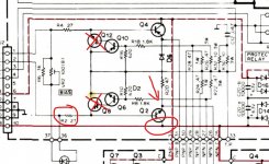
Lets stick with that odd reading across the 27 ohm. You need to recheck that result because having such a high voltage points to a problem around the driver transistor Q2.
It suggests the transistor is possibly very low gain or perhaps has an open circuit collector connection/junction. It means the output transistor alone in loading the bias circuit and doing all the work. That would pull the STV voltage down.
Check for any dry joints on the transistor first.
The transistor should have positive supply voltage on the collector and you should also see approx 0.6 volts between base and emitter.
Be very careful measuring because just one slip of the probe and it all goes bang.
Also always turn the bias preset back to minimum bias before powering up again.
Attachments
Ok, here are the results: i re-checked the R-1, 2, 3, and 4 and R-4 is .01MV and R-2 104MV, still high. Did the voltage change because of the playing with the trimpot? IDK...
Checked between Base and Collector of Q-2 (2SC-1913), and got .652V
Got +.4 Volt from ground to Collector of Q-2.
I will remove Q-2 today and test it with my Atlas and post the results.
Checked between Base and Collector of Q-2 (2SC-1913), and got .652V
Got +.4 Volt from ground to Collector of Q-2.
I will remove Q-2 today and test it with my Atlas and post the results.
The driver transistors Q2 and Q4 form what is effectively a Darlington Pair with the output transistors.
That means that they behave a bit like a single transistor of very high current gain... and this is where the high reading across R2 comes into play. That voltage means nearly 4 milliamps is flowing into the base of Q2 and that in turn should be getting amplified and turning the output transistor on.
Even with the bias set high, the current should still be low in that resistor.
Your readings 🙂 You mean between base and emitter, not collector.
The base/emitter voltage should always be around 0.65 volts give or take a little.
Sorry! i goofed 🙁 Took these new measurments twice; Base to Emitter: .669MV Base to Collector: .664MV
That's no problem 🙂 but you should have something approaching supply voltage between base and collector. The collector goes to the positive supply rail.
Make sure there is no break in the print anywhere. A missing supply to the collector of that driver transistor would give the symptoms you have because the B-E junction is then just like a diode... so the amp still works but it is massively lacking current gain on that half of the output stage.
Make sure there is no break in the print anywhere. A missing supply to the collector of that driver transistor would give the symptoms you have because the B-E junction is then just like a diode... so the amp still works but it is massively lacking current gain on that half of the output stage.
Hahaha! Mooly! you'r the best!. You found the problem!. There was a faint trace lift/ crack right there on the collector of Q2!.
I tried to adjust the Bias but, i have to find a lower resistance value for the paralell trimpot resistor as now, with the new Bourns, the OEM 33ohms, is not enough. I now overshoot!.
On the left channel, i had to change the 33Ohms for an 18 and the Bias was dead on, near middle of trimpot.
So, that's why the heat sink, for that pair of drivers was around 13C colder then Left channel.
Thank you sooo much Mooly!, ill report back after the biasing is done. Have to find a couple of 15 to 25 ohms 1/4watt dudes!.
Ok, i tried a 20ohms resistor, in place of the OEM 36 ohms, as parallel to trimpot and, the Bias voltage skyrockets 🙁 . I pre-adjusted the pot for minimal bias (all the way to almost zero ohms), and tried the 36ohms first but no joy. I know that reducing resistance (less ohms) reduces bias voltage.
I shut down the amp immediatly as it climbs fast and steaddy to ten times the wanted 18MV and that even before the relay closes.
I shut down the amp immediatly as it climbs fast and steaddy to ten times the wanted 18MV and that even before the relay closes.
I know I am a minority view here but there is no "deaf earing " the fact you are trying to replace Varistors ---yes made by Pioneer that's what a STV-4H is .
Please read this guys logical and practical work to replace them with ordinary diodes and please read the whole post not gloss over it /speed read before giving you opinion.-
Replacing The STV-3H and -4H Diodes | Audiokarma Home Audio Stereo Discussion Forums
Please read this guys logical and practical work to replace them with ordinary diodes and please read the whole post not gloss over it /speed read before giving you opinion.-
Replacing The STV-3H and -4H Diodes | Audiokarma Home Audio Stereo Discussion Forums
Ok, i tried a 20ohms resistor, in place of the OEM 36 ohms, as parallel to trimpot and, the Bias voltage skyrockets 🙁 . I pre-adjusted the pot for minimal bias (all the way to almost zero ohms), and tried the 36ohms first but no joy. I know that reducing resistance (less ohms) reduces bias voltage.
I shut down the amp immediatly as it climbs fast and steaddy to ten times the wanted 18MV and that even before the relay closes.
Lets start with basics to begin with.
Does the bias hold at zero or very nearly so with the trimmer on minimum resistance?
If there is doubt then with the amp OFF, measure resistance across the trimmer to be sure it really is at zero ohms.
Can you be sure the resolution of the trimmer is good?
In other words can you turn it to say 5 or 10 ohms resistance or does it jump from zero to something a lot higher?
Assuming it does hold at zero then measure the voltage across the STV and see if it alters over time. Compare with the other channel. Only do this if the bias isn't to high.
If the bias is to high to be safe then do a very quick voltage comparison between the two STV's and write the values down. They should be very close.
I know I am a minority view here but there is no "deaf earing " the fact you are trying to replace Varistors ---yes made by Pioneer that's what a STV-4H is .
Please read this guys logical and practical work to replace them with ordinary diodes and please read the whole post not gloss over it /speed read before giving you opinion.-
Replacing The STV-3H and -4H Diodes | Audiokarma Home Audio Stereo Discussion Forums
We haven't replaced or even suggested replacing these STV's (yet 😉) so we're not in that territory just at the moment.
- Home
- Amplifiers
- Solid State
- Kenwood KA-801 amp, can't adjust bias!...