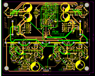
After LOT of experimenting, Line Amplifier updated, pcb drawing finished... I added a Pot for "harmonic content manipulation". It`s clearly measurable and how it`s going to affect the sound, I`ll hear when I make it 😀 .
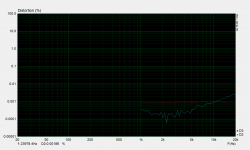
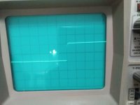
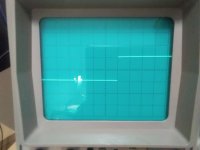
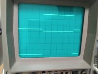
Before I make final proto, some measurement of the updated circuit. Measurements of 2nd (blue) and 3rd(red) harmonic vs frequency, 2V-peak at 600 Ohms load, with 5 different Pot positions, from min to max:
Before I make final proto, some measurement of the updated circuit. Measurements of 2nd (blue) and 3rd(red) harmonic vs frequency, 2V-peak at 600 Ohms load, with 5 different Pot positions, from min to max:
Attachments
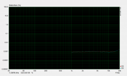
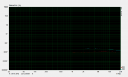
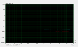

Line Amplifier with +/-15V power supply, measurements for 4Vpp at 600 ohms load.
First two graphs are for R8-10K and other two graphs for R8-100R.
It`s interesting how critical value of that resistor is to the distortion and 2nd and 3rd harmonic relation. 🙂
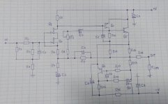
In a conventional complementary feedback pair amplifier output half, R8 would connect to the top of R11 in that way the signal voltage dropped across R11 would be feedback to Q3 emitter and base.
If this signal is applied solely to the emitter this is going to affect the base voltage giving more variation than desirable in base to emitter voltage.
I've tried and measured evey combination and variation of the circuit I could think of, last schematic is not final, but R8 remained on the output, R11 is low value anyway.
Harmonic tuning pot is in another feedback loop as you could see at measurements in previous post, third harmonic is constant, and 2nd is adjustable.
Hi Bogdan,
Clever circuit!
Compensation is always an issue; there are so many choices, but all of them influence the sound quality.
Looking at your #19 schem, have you tried phase lead, starting with 15pF, from collector of Q2 (master VAS) to source of J1, the fb node?
You might also consider a bypass across R5, you could start here with 100pF.
R8 is an excellent idea because it ensures the master VAS transistor is always on, reducing the artefacts which are a big problem with CFPs.
Finally, given the attempt to reduce THD is the primary concern, what advantage do you see in trying for a monotonic harmonic profile? Some believe this is a waste of time; low THD is the key.
Hugh
Last edited:
Hugh, the compensation is different, as I said, tried lot of things... it's an experiment, I like to have some kind of "sound control" I'll see if adjustable 2nd harmonic is usable or not.
I don't think It's all about lowest distortion, for ones that do there are lot of opamps available..
I don't think It's all about lowest distortion, for ones that do there are lot of opamps available..
im looking for a quasi buffer to be used as a zero gain headphone amp. Could the output stage of your very first schematic serve that purpose? Signal input going into the base of Q2. No feedback.
im looking for a quasi buffer to be used as a zero gain headphone amp. Could the output stage of your very first schematic serve that purpose? Signal input going into the base of Q2. No feedback.
Didn't try it as a buffer, maybe should be tweaked for stability in that case..


- Home
- Amplifiers
- Solid State
- Asymmetric Gain Stage experiments