Hello guys,
I'm new to the forum, so let me know if I have a better place to post this thread please!
So, I just tried to post smth but lost everything, so I'm trying again.
The explanation of the phase 90 by electrosmash is very well done, but for a college student who's doing a phaser inspirated on that schematic as a final project, may be a little "not in depth".
In the output of the phaser, why is it that is there a transistor and not an op-amp? Is there a specific reason or not really?
Also (I will be posting the schematic in the index), what is the R7 doing there? R8 and R16 are clearly wheighting how much of the input and the output is mixed, but R7...
And R4, what is it doing? In the simulations in LTSpice what I got was a diminished gain when I changed it, and that's all.
Thank you and sorry anything,
Fred
Attachments
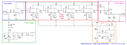
Q1 with R16, R8, R7 forms an inverting mixer, the kind of which you could also build with another opamp (while probably not requiring R values quite as high as 150k either - 10k-22k may very well do). If so, the Vref zener should probably be changed to something closer to 4.1-4.5 V (with somewhat higher R15) assuming it doesn't interfere with the trimming action too much.
Take advantage of dual and quad opamps for reduced board space. Consider e.g. TLE206x types as a potential upgrade as well (way higher output driving capabilities, not as slow and somewhat less terribly noisy to boot).
Take advantage of dual and quad opamps for reduced board space. Consider e.g. TLE206x types as a potential upgrade as well (way higher output driving capabilities, not as slow and somewhat less terribly noisy to boot).
In 1972, an opamp cost money, a transistor cost less, and did this job fine.
Ok basically explained!
R7 biases the transistor.
R4 is load for the transistor.
Okk that helps, but What you mean by load? And why does it have to have one? The load at the end of the output of the pedal isn't enough?
Q1 with R16, R8, R7 forms an inverting mixer, the kind of which you could also build with another opamp (while probably not requiring R values quite as high as 150k either - 10k-22k may very well do). If so, the Vref zener should probably be changed to something closer to 4.1-4.5 V (with somewhat higher R15) assuming it doesn't interfere with the trimming action too much.
Take advantage of dual and quad opamps for reduced board space. Consider e.g. TLE206x types as a potential upgrade as well (way higher output driving capabilities, not as slow and somewhat less terribly noisy to boot).
Thank you very much! I'm already tjinking on how I'm gonna do this, but why 4.1-4.5 V? Makes too much diference?
If I am using an op amp in the output, I will for certain use 3 dual op amps, but first I have to decide what I'm gonna do on the LFO part.. I've been researching and found that the LFO as it is, is really unstable, and I'm thinking bout using a Lm339 to generate a square and then using an integrator to get a triangular wave.
What do you experient guys/girls have to say about this? Knowing that I would like the amplitude of the LFO to be changed as I wish (turning the bias pot that feeds both the LFO and the gates of the FET'S), I am imagining it would be possible, but I don't know yet.
Greetings, Fred
> What you mean by load? And why does it have to have one?
Do you know how to make a transistor amplifier? A naked transistor just sits there. At best it can pull one way not the other. We have to wire it in a "fair fight" with another part (resistor is cheapest) to get a both-ways swing. There's Books. YouTube clips.
____________________
> Vref zener should probably be changed .....advantage of dual and quad opamps for reduced board space. ...e.g. TLE206x .... higher output driving capabilities, not as slow ......
Yeah well, there is much to criticize in the Phase 90 from 1972 but after 48 years of steady demand maybe we can keep it on the job without a gut transplant. And there are "improved P90s". All the way to ADC/DAC instead of goofy JFET dividers.
BJT instead of op-amp (and wasn't TL061 those days, likely '741) saves a whole dollar. The P90 sold very well. Not a million, but enough to buy a house, just using one cheaper part.
uA741 $1.59
BJT $0.10-$0.30
(over a buck saved!)
FYI:
12AX7 $1.79
6L6GC $3.99
-----------------------------------
The biasing of that virtual earth summing mixer is odd/clever and I never bothered to work it out by hand. I happened to have a similar thing in my temp sim, so I ran it.
It is well known that the "5.1V" (@ what mA?) Zener in the P90 tends to run nearer 4.8V so I used that; but a little thumb-squint says it is not sensitive. It runs on quite a low voltage but will do 2V peak in 200k easy which is ample for guitar-cord effects.
Attachments
>
Do you know how to make a transistor amplifier? A naked transistor just sits there. At best it can pull one way not the other. We have to wire it in a "fair fight" with another part (resistor is cheapest) to get a both-ways swing. There's Books. YouTube clips.
Yes you're right, I've already learned transistors but ironically as it seems now, my practice classes were given at home (with us doing simulation on software) because of Covid. Maybe I didn't get it so right.
Just to clarify best, that load resistance would be the collector resistance right? Or would it be the resistor that receives the current when it goes out of the collector? (It is a common emitter right?)
>
____________________
> Vref zener should probably be changed .....advantage of dual and quad opamps for reduced board space. ...e.g. TLE206x .... higher output driving capabilities, not as slow ......
Yeah well, there is much to criticize in the Phase 90 from 1972 but after 48 years of steady demand maybe we can keep it on the job without a gut transplant. And there are "improved P90s". All the way to ADC/DAC instead of goofy JFET dividers.
keep it on the job without a gut transplant should mean not changing too much, not having bigger worries, right?
You are actually making me more doubtful each time hahah, you're saying that instead of the JFET's one can use ADC/DAC's ?? That seems yummy (maybe not the yummiest because I already ordered the JFET's).
As I already noticed you're a kind person that appears on every forum I post, I would ask you, what would you recommend me "modding" in the P90? putting feedback resistance/more stages/ammount or depth knob/width knob? Is there any on this list that seems too complicated/not so good?
Thank you
BJT instead of op-amp (and wasn't TL061 those days, likely '741) saves a whole dollar. The P90 sold very well. Not a million, but enough to buy a house, just using one cheaper part.
uA741 $1.59
BJT $0.10-$0.30
(over a buck saved!)
FYI:
12AX7 $1.79
6L6GC $3.99
-----------------------------------
The biasing of that virtual earth summing mixer is odd/clever and I never bothered to work it out by hand. I happened to have a similar thing in my temp sim, so I ran it.
It is well known that the "5.1V" (@ what mA?) Zener in the P90 tends to run nearer 4.8V so I used that; but a little thumb-squint says it is not sensitive. It runs on quite a low voltage but will do 2V peak in 200k easy which is ample for guitar-cord effects.
That's some valuable info, and I'm thinking bout staying with the transistor, it all depends on wether i'll use a TL072 on the LFO or not. If note, maybe I'll try it on the output (the cost isn't that higher).
As for the valves and triodes, I can't say much because I haven't learned a thing in school, and am not planning to lose too much time, but gain it hahah so not using it now (the cost there makes diff).
I also am tring to understand that biasing, maybe I'll do some simulation specifically for that. Would you recommend me doing just like you did, with 4.8 Volt and only connecting the transistor and the resistances? Or trying to do math?
- Home
- Design & Build
- Parts
- Phase 90 - Help with the Output part please!