I´ve get an old JVC A-X2 Super-A integrated amplifier from a friend to be repaired. He said that one channel was burnt. When I tested the amp, the right channel has the two power transistors shortcircuited (both have B-C-E measured 0 ohms).
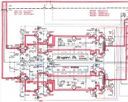
I've attached in this thread a picture of the affected amplifier circuit.
Also both R644 0.22 ohm 5W combined fuse resistors between emitters are open, and the same occurs with the R640 resistor.
I replaced all these components and put a proper fuse for my AC voltage (220 VAC) whose value was 2 A, and also connected headphones as a load to the amp. Loudspeakers are disconnected.
The original damaged transistors were 2SA1076 and 2SC2565 which I replace with 2SA1943 and 2SC5200, respectively.
When I turn on the equipment, the fuse immediately burns out. Then I mistakenly replace the fuse with one whose value was 5 A and turn on again. Immediately, the power transistors and resistors get in the same condition: transistors all have 0 ohms between B-C-E and resistors are opened, and the circuit get smoke.
I have tested all the circuit components and are all OK; all have the proper values. The only component that I've not tested was the IC602 (VC5022), the Super-A chip. I suspect that this IC is the problem.
What are the problem with this amp? Thank you all.
Diego
Attachments
you should be using a light bulb tester when testing any amplifier. The incandescent light bulb is in series with the amplifier. If the amplifier works the bulb will be dim. If there is a fault in the amplifier the bulb will be bright and protect the amplifier from more damage. The transistors are failing most likely from too much bias. Did you check the trim pot for proper operation as well as the thermistors R629 R622 and the bias transistors X613 X614? I am guessing that the chip VC5022 provides some type of dynamic class A bias or current limiting, After a quick search I couldnt find a data sheet for it.sheet for it.
multisync, I have tested termistors an the transistors you mentioned and are all OK. With respect to the incandescent light bulb, I have to connect it in series with the amplifier AC power supply, i. e. 220 VAC in my case?
Is also a pooch screw going to 1943/5200 1494/3858 would be the go to there
Wonder how unobtanium the VC5022 is... an open circuit in there will prove catastrophic- the main bias is clamped through it...
So. An open will result in effectively a short across power supply through outputs... ouch
Wonder how unobtanium the VC5022 is... an open circuit in there will prove catastrophic- the main bias is clamped through it...
So. An open will result in effectively a short across power supply through outputs... ouch
Well, thank you SVI2004A. I removed the VC5022 and tested it. Between all pins of it I measure infinite resistance, with the exception of the pins 8 and 9, where the resistance is about 18 Megohms.
This IC should connect bias regulation circuit (components connected to pins 2 and 9) to pins 1 and 5 - (output signal Feed) - pin 5 is connected to output - and internally would be a high speed stabistor array (for the Super A operation)
How does the working channel IC meter up in comparison?
How does the working channel IC meter up in comparison?
Do check outputs drivers and that X614 is ok after replacing super A ic
Remember to follow bias setting after repair - refer manual
Remember to follow bias setting after repair - refer manual
Hi - the VC5022 IC appears to be available via eBay and Aliexpress but be warned - the three we ordered all turned out to be faulty or fake. You can remove the IC and short pins 1&2 and 5&9 but will lose biasing.
It does work though, and whether you can live with the sound is up to you ... can't see much of a difference on the 'scope.
Changing the preset to a higher value does allow for the bias to be set but has proven to be unstable so far. Will update here if we find a solution.
It does work though, and whether you can live with the sound is up to you ... can't see much of a difference on the 'scope.
Changing the preset to a higher value does allow for the bias to be set but has proven to be unstable so far. Will update here if we find a solution.
if you take out the driver & output Transistors and test the amp with the VC5022 in place, you should have about 2.4v across the pins going to the driver transistors
Thanks for the tip ... will see if we can get oneHello, I understand that the LA2500 can replace the VC5022
Hi - yes we did manage to fix it. The LA2500's seemed to do the trick. Hope this helps.

- Home
- Amplifiers
- Solid State
- JVC A-X2 Super-A integrated amplifier - Right channel power transistors burnt