Hi,
by comparing mainly weights of OPTs with amorphous cores I thought this one twice, as a double c-core, should be enough core to realize full frequency bandwidth in a 30-40W 3k/4Ω PP OPT (...more than 1kg of 25µm amorph. Fe each channel)
Regardless of the risk, the quality of the cores could be too bad... would you agree?
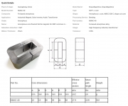
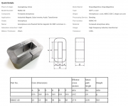
It is a cheap China-clone of Hitachis AMCC40. Here is the link or alternatively to this huge confusing site I also put the important parts of the page into a picture....

price: 12€/14$ ...double c-core each channel: 48€/56$
KMAC-40 amorphous c core, Zhuhai King Magnetics Technology Co., Ltd. on Alibaba.com
Or maybe....
Because BudP explains in this thread among (much!) others that the improvement by amorphous cores will be just very slightly as long as the rest of the system isn't also on highest level -especially speakers. So should I maybe rather get something like 2kg each channel of 0.3-mm silicon-steel because there won't be any difference to amorphous/nanocrystalline cores noticeable as long as I am still experimenting and learning basics and not climbing peaks yet? If I got it right then for lower frequencies amorphous material would then even be a disadvantage compared to a much bigger (for same money) 0.3mm-SiFe core.... Do you agree?
Thank you alot!
by comparing mainly weights of OPTs with amorphous cores I thought this one twice, as a double c-core, should be enough core to realize full frequency bandwidth in a 30-40W 3k/4Ω PP OPT (...more than 1kg of 25µm amorph. Fe each channel)
Regardless of the risk, the quality of the cores could be too bad... would you agree?
It is a cheap China-clone of Hitachis AMCC40. Here is the link or alternatively to this huge confusing site I also put the important parts of the page into a picture....

price: 12€/14$ ...double c-core each channel: 48€/56$
KMAC-40 amorphous c core, Zhuhai King Magnetics Technology Co., Ltd. on Alibaba.com
Or maybe....
Because BudP explains in this thread among (much!) others that the improvement by amorphous cores will be just very slightly as long as the rest of the system isn't also on highest level -especially speakers. So should I maybe rather get something like 2kg each channel of 0.3-mm silicon-steel because there won't be any difference to amorphous/nanocrystalline cores noticeable as long as I am still experimenting and learning basics and not climbing peaks yet? If I got it right then for lower frequencies amorphous material would then even be a disadvantage compared to a much bigger (for same money) 0.3mm-SiFe core.... Do you agree?
Thank you alot!
Last edited:
A single AMCC40 is enough for a line level transformer.
For a 40W PP you'll need at least 9sq.cm
Of course it depends of how much losses, parasitics and winding difficulty you will tolerate. Larger cores are easier to work with.
Amorphous BH knee starts at 1T, this should be your maximum. Forget about the classic 1.56T mentioned.
From the POV of audibility, it's definitely worth it. Nanocrystalline even more.
For a 40W PP you'll need at least 9sq.cm
I would actually not be too far away from that I guess....

A_Fe = A*D * 2 = 13mm * 35mm * 2 = 4,55cm² * 2 = 9,1cm²
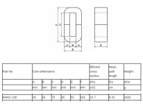
You probably didn't see I would go for double c-cores and also I just noticed that in the table the values (or titles) of the columns A_Fe and l_Fe need to be swapped.
The KMAC-100 would be 24€ each -> 96€ in total....
A_Fe = 16mm * 45mm * 2 = 14,4cm²

So this one would do the job just perfectly?
From the POV of audibility, it's definitely worth it. Nanocrystalline even more.
How big should A_Fe be for 40W PP if nanocrystalline material is used?
Last edited:
First, you need to design a transformer, then look for a core with approximately required dimensions, and at last adjust to available material. Don't put a cart before horse. Even if you stack multiple cores to the required cross-section area, the window area may not be sufficient to accommodate large turns count typical for audio transformers. These cores made for transformers/chokes from solar inverters, which are high frequency, and therefore, have low turns count.
Stacking factor for Chinese-made amorphous and nanocrystalline cores is about 75%, so real cross-section area is only 75% of the physical one.
Shipping costs and customs/taxes are also significant contributions to the bottom line.
Stacking factor for Chinese-made amorphous and nanocrystalline cores is about 75%, so real cross-section area is only 75% of the physical one.
Shipping costs and customs/taxes are also significant contributions to the bottom line.
First, you need to design a transformer, then look for a core with approximately required dimensions, and at last adjust to available material.
The first step you explain I think I did...
Or do you mean something else when you say "design a transformer"?30-40W 3k/4Ω PP OPT
What I am asking for help is the second step in your explanation. I estimated the core dimensions by comparing professional OPT. Because cores masses were the only magnitude I compared to estimate my core dimensions I was really lucky 50AE told me in this thread about the importance of magnetic cross sections. When I noticed the quantity-symbol A_Fe I heard a bell ringing that I had to use this in formulas.... formulas where also permability, saturation, air gap, windings, wire thickness were important. Do I have to be able to calculate myself through the electromagnetical storyline of transformers again or is it enough to just make some experiences to be able to estimate core dimensions and in the beginning ask e.g. you guys?
Oh... sure...acutally.... but I didn't consider this at all -that all the windings as well as the bobbin frame must fit through the c-gap which is only 2cm x 7cm at the even bigger KMAC-100. Thanks a lot for immersing yourself into this far enough to notice this! Annother and not less important aspect of dimensioning OPT cores.Even if you stack multiple cores to the required cross-section area, the window area may not be sufficient to accommodate large turns count typical for audio transformers.
Isn't it the same material and just slightly different measures? But this I have to get deeply into because for the music I like most, low freqs are absolutely essential...These cores made for transformers/chokes from solar inverters, which are high frequency, and therefore, have low turns count.
I wondered already why they make their product worse in this table where all the A-Fe values seemed to be a bit too small. This bit is exaclty 25%.... Thank you a lot again, it seemes you really kindof analysed what the important key aspects are I didn't get yet. Luckily I didn't have to learn the hard way or rather the expensive way in this case.Stacking factor for Chinese-made amorphous and nanocrystalline cores is about 75%, so real cross-section area is only 75% of the physical one.

To be honest I took it for actually granted not to be charged for shipping because they send from China.... But it seems yoiu are right....Shipping costs and customs/taxes are also significant contributions to the bottom line.
tbc
I can calculate winding parameters based on the requirements and material you have, yet right now there is not enough data to work with. IMHO first prototype better to build with surplus GOSS (silicon steel) cores, get some experience, and only then order quite expansive amorphous. And here is why.
First - need precise data,
Your description is somewhat ambiguous, 30-40W 3k/4Ω PP OPT doesn't fit well, for example for 40W 6L6GC you will need 6.6K, or maybe 5K with cathode feedback. El84M/6P14P-EV need 8K. KT88 is OK with 3.3K but need 60W.
So do you target EL34? A range between 30W -:- 40W, 3K -:- 4K is a BIG difference.
Need UL, cathode feedback? Then a more complex layout, larger window height.
Remember, need a bobbin, it will eat some space, too.
A blueprint of the bobbin design attached. Cut them from 2mm paxolin, presspan, FR2, or FR4 with a CNC router or even sheet metal scissors.
2*2mm deducted from window height and -2 mm on each sidewall. Internal corners of C-cores slightly rounded, so extra 2mm clearance on each side. Real winding length -8mm of datasheet core length.
Here are very informative pages to start with:
output-trans-pp-calc-1
EI cores usually have a very small window area, yet you can stack them at any thickness needed, and therefore, reduce the number of turns. Out of 3 surplus power transformers, you can (usually) assemble 2 output units. From the Patrick Turner pages (link above), you get a clue of your first design.
Good luck have fun !
Attachments
I would actually not be too far away from that I guess....
View attachment 873435
A_Fe = A*D * 2 = 13mm * 35mm * 2 = 4,55cm² * 2 = 9,1cm²
You probably didn't see I would go for double c-cores and also I just noticed that in the table the values (or titles) of the columns A_Fe and l_Fe need to be swapped.
The KMAC-100 would be 24€ each -> 96€ in total....
A_Fe = 16mm * 45mm * 2 = 14,4cm²
View attachment 873433
So this one would do the job just perfectly?
How big should A_Fe be for 40W PP if nanocrystalline material is used?
Wrong.
Afe is not twice A*D but just A*D.
Besides, A*D is the physical core area; effective Afe is less.
For a AMCC40, it is 3.64 cm².
A double core would give 7.3 cm² which is not enough for a quality 40W PP transformer.
A double AMCC100 has 11.5 cm² of Afe.
A double AMCC80 with just over 10 cm² of Afe will do.
Last edited:
Sorry for late reply, got some face physical trauma issues 😀
Other folks did reply you quite accurately.
For a P-P transformer, where it will need to widthstand little to none disbalance DC current in the primary, you can calculate the maximum power from the POV of Vac swing only.
First you should choose a maximum flux density. I recommend 1.0T for amorphous and nanocrystalline and 1.4T for GOSS.
Secondly, choose your lowest frequency for the maximum power. I go for 25Hz, some folks choose 30Hz, others go well beyond 20Hz.
If we choose a frequency of 25Hz, amorphous core of 9sq.cm and leaving some 0.2T headroom for DC disbalance, which translates to 0.8T max swing, then by using the formula:
Bac = Vrms / f*4.44*Afe*T
Afe - core surface area in meters
f - working frequency
T - number of turns needed.
Bac = flux density in Tesla, we are targeting 0.8T
But first we need to find primary voltage swing needed for an example of 40W of power
Vrms = sqroot(Pmax * Z pri)
Pmax = 40W
Zpri = 4000R
Vrms = 400V
Then, let's go back to the flux density formula:
Bac = Vrms / f*4.44*Afe*T
0.8T = 400 / 25*4.44*0.0009*T
0.0999T = 500
T = 5000
Guess what. You need 5000 turns for a 9sq.cm amorphous C core, or 3333T for GOSS, if we use a flux density of 1.2T, to get 40W at 25Hz. Ah, and forgot to include ohmic losses!
For beginners I do not recommend winding a transformer with more than 3000 primary turns due to harder to control parasitics, the employ of special dielectrics and more strategies.
Next comes the calculation of wire gauge vs. windows, ohmic losses, leakage inductance, calculating parasitic capacitances, etc.
- Home
- Amplifiers
- Tubes / Valves
- Are these OPT-cores big enough?
