Hey folks,
Posting here again, this time asking for specific advice. I'm new to tube amps and have a very fuzzy general education in analog electronics from a couple of decades ago that I never used - mostly digital and software.
I started off trying to make a 12AX7/KT88 hi-fi amplifier a few months back(with a lot of pointers from you guys). I built a prototype on plexiglass and IMO it sounds pretty good. I don't have too many ways to objectively measure its capabilities other than eyeballing sine waves on the oscilloscope. My ears were not offended though.
So after building that and running it off an old iPhone, and then off another device(boombox radio headphone output) with a stronger output signal, I could see that there was room for improvement in terms of overall gain.
That schematic is long gone, especially since I did so many in-flight tweaks on the prototype. I wanted to add another stage and I'm back in LTspice land for a while. The current schematic I know has several flaws, but the old circuit was roughly the same, minus the 12AU7 stage, the 12AX7 stage was biased using an IR LED, and the feedback loop was local around the KT88 and not global.
I have a couple of specific questions, and I'd preferred not to be spoonfed, I genuinely want to thoroughly understand this so I don't keep asking dumb questions.

1) How should I measure gain with this? I'm using an 8ohm resistor on the secondary of the OT and using the .ac op to get frequency response. The gain measured from that point comes out to a little over 16dB, but this is after a 25:1 volt reduction on the OT. Where would you folks measure this in LTSpice?
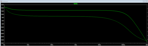
2) Speaking of looking at the gain, here is the frequency response as reported by R10(the 8 ohm):

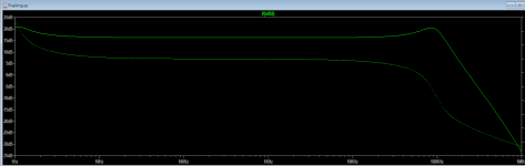
One thing to note is that the rolloff at higher frequencies is only because of C3 on the feedback loop. I feel like this is unnatural and would not work out if this was under a reactive load. Here's the response without C3:

I've found that this roughly 85kHz bump was introduced after the first 12AX7 stage. If I break the feedback loop completely, it goes away, but the frequency response starts to roll off around 18kHz-ish(-3dB) which is no good.
I can alleviate this by increasing the feedback resistor value, but then I run into another problem.
3) I asked this in another thread, how much negative feedback is too much? The problem is that I had a good thing going with my original 12AX7/KT88 design, but I got greedy and wanted just a little bit more gain, because I empirically was able to see it had more headroom without much compromise, and I'm trying to make that a "natural" part of the circuit. Now I have too much gain and I'm using a lot of feedback to keep it from clipping each stage, and it seems this is negatively impacting my frequency response and phase.
Anyway, I would appreciate any pointers on the 3 questions, plus any gentle feedback(but not too gentle) on the design itself. It's still a WIP and I still haven't done a final once over on the math besides biasing and voltage swings yet. Definitely point out any WTFs!!
Thanks folks.
Posting here again, this time asking for specific advice. I'm new to tube amps and have a very fuzzy general education in analog electronics from a couple of decades ago that I never used - mostly digital and software.
I started off trying to make a 12AX7/KT88 hi-fi amplifier a few months back(with a lot of pointers from you guys). I built a prototype on plexiglass and IMO it sounds pretty good. I don't have too many ways to objectively measure its capabilities other than eyeballing sine waves on the oscilloscope. My ears were not offended though.
So after building that and running it off an old iPhone, and then off another device(boombox radio headphone output) with a stronger output signal, I could see that there was room for improvement in terms of overall gain.
That schematic is long gone, especially since I did so many in-flight tweaks on the prototype. I wanted to add another stage and I'm back in LTspice land for a while. The current schematic I know has several flaws, but the old circuit was roughly the same, minus the 12AU7 stage, the 12AX7 stage was biased using an IR LED, and the feedback loop was local around the KT88 and not global.
I have a couple of specific questions, and I'd preferred not to be spoonfed, I genuinely want to thoroughly understand this so I don't keep asking dumb questions.
1) How should I measure gain with this? I'm using an 8ohm resistor on the secondary of the OT and using the .ac op to get frequency response. The gain measured from that point comes out to a little over 16dB, but this is after a 25:1 volt reduction on the OT. Where would you folks measure this in LTSpice?
2) Speaking of looking at the gain, here is the frequency response as reported by R10(the 8 ohm):
One thing to note is that the rolloff at higher frequencies is only because of C3 on the feedback loop. I feel like this is unnatural and would not work out if this was under a reactive load. Here's the response without C3:
I've found that this roughly 85kHz bump was introduced after the first 12AX7 stage. If I break the feedback loop completely, it goes away, but the frequency response starts to roll off around 18kHz-ish(-3dB) which is no good.
I can alleviate this by increasing the feedback resistor value, but then I run into another problem.
3) I asked this in another thread, how much negative feedback is too much? The problem is that I had a good thing going with my original 12AX7/KT88 design, but I got greedy and wanted just a little bit more gain, because I empirically was able to see it had more headroom without much compromise, and I'm trying to make that a "natural" part of the circuit. Now I have too much gain and I'm using a lot of feedback to keep it from clipping each stage, and it seems this is negatively impacting my frequency response and phase.
Anyway, I would appreciate any pointers on the 3 questions, plus any gentle feedback(but not too gentle) on the design itself. It's still a WIP and I still haven't done a final once over on the math besides biasing and voltage swings yet. Definitely point out any WTFs!!
Thanks folks.
Attachments
By the way, the output transformer is a Hammond 1628-SEA with a 5k impedance with multiple outputs:
1628SEA - Hammond Mfg.
Sorry that's not obvious from the schematic.
1628SEA - Hammond Mfg.
Sorry that's not obvious from the schematic.
This is not answers to your questions, but it is another hint to reliability.
Generally for a KT88 that has self bias (you do, R11) . . .
The maximum g1 resistance is:
Up to 35 Watts plate + screen dissipation, 470k (your R2 is 1 Meg)
More than 35 Watts plate + screen dissipation, 270k (your R2 is 1 Meg)
Prevent thermal run-away
Prevent Red Plate
follow the maximum g1 resistance rules.
(some KT88 are strong; some KT88 may break)
Last edited:
I think you have to read some on the topic of phase-shift caused by OPT's, and the effects of it (and cures) on NFB with the OPT in the loop. If you simulate NFB, it will only give good results if all the parameters of the OPT are part of the simulation.
This is not answers to your questions, but it is another hint to reliability.
Generally for a KT88 that has self bias (you do, R11) . . .
The maximum g1 resistance is:
Up to 35 Watts plate + screen dissipation, 470k (your R2 is 1 Meg)
More than 35 Watts plate + screen dissipation, 270k (your R2 is 1 Meg)
Prevent thermal run-away
Prevent Red Plate
follow the maximum g1 resistance rules.
(some KT88 are strong; some KT88 may break)
This is definitely one of the flaws in the schematic. My original 12AX7/KT88 schematic(and current prototype) actually has a 220k in that spot, I just double checked. Going to fix the schematic now before I do a re-build and really screw it up. Thanks for pointing that out!
I think you have to read some on the topic of phase-shift caused by OPT's, and the effects of it (and cures) on NFB with the OPT in the loop. If you simulate NFB, it will only give good results if all the parameters of the OPT are part of the simulation.
Thanks. Are you suggesting the phase shifts and response I'm seeing are probably exclusive to LTSpice and my poor representation of the OPT, and I may not see that in a real build, or vice versa? Like I mentioned, my physical prototype only had a feedback loop on the KT88(few hundred K) and I have not actually tried to tap off the secondary yet.
PCL200 is correct. There's not "enough" info in the sim to tease out phase shift problems, and even using a resistive load on the output doesn't adequately simulate the reactive nature of a speaker load.
You can read up a ton on output transformer phase shift and how to approximate a speaker load with resistors, inductors, and capacitors, or you can move your feedback loop so that it is local only.
You can read up a ton on output transformer phase shift and how to approximate a speaker load with resistors, inductors, and capacitors, or you can move your feedback loop so that it is local only.
All the technical design aspects are way over my head and I know nothing about using Spice. So I tend to approach things in a much more simplistic manner.I started off trying to make a 12AX7/KT88 hi-fi amplifier a few months back . . . So after building that and running it off an old iPhone, and then off another device(boombox radio headphone output) with a stronger output signal, I could see that there was room for improvement in terms of overall gain.
The problem is that I had a good thing going with my original 12AX7/KT88 design, but I got greedy and wanted just a little bit more gain, because I empirically was able to see it had more headroom without much compromise, and I'm trying to make that a "natural" part of the circuit. Now I have too much gain and I'm using a lot of feedback to keep it from clipping each stage, and it seems this is negatively impacting my frequency response and phase.
If a 12AX7 was not quite enough gain and adding a 12AU7 (mu 20) produced too much gain I would be looking for a tube that had less gain than the 12AU7. Personally, I don't mind using tubes that are not well known, as long as they aren't unobtainium or expensive.
While I haven't used it yet, you might consider something like the 6CY7, which is a dissimilar triode. I'd leave what is normally considered the "input" section disconnected and use only the "output" section which has a mu of 5 and a low plate resistance of only 920 ohms.
https://tubedata.altanatubes.com.br/sheets/093/6/6CY7.pdf
Another approach would be to keep the 12AU7 - or some other tube with mu 20 like the 6CG7 or 12BH7 - and replace the 12AX7 with a lower gain tube from the same family like the 12AY7 (mu 44), 12AT7 (mu 60) or 5751 (mu 70). Actually, you could use the "input" section of the 6CY7 here too as it has a mu of 68.
Once the amp is built, do you plan on using your old iPhone as the source? If so, I assume you plan on controlling the volume from the phone. From what I've read, phones put out a pretty low signal compared to, say, a CD player. So, obviously, that affects the design.
If other sources, which don't have their own volume control, will be used then you'll need to either add one to the amp or use a preamp so you should take that into account too.
There seem to be numerous SE KT-88 schematics out there. Have you considered building any of them? I don't know how well it would work with a low signal input like an iPhone, but here's a thread about one that seems to be well regarded.
Kegger/blueglow kt88 project | Audiokarma Home Audio Stereo Discussion Forums
Or you can build it, measure the response and adjust feedback accordingly.
I definitely will. My first prototype I more or less went cowboy on, didn't even have a variac at the time. I'm not doing it that way again. I was honestly expecting some people to scream in horror at the design.
All the technical design aspects are way over my head and I know nothing about using Spice. So I tend to approach things in a much more simplistic manner.
If a 12AX7 was not quite enough gain and adding a 12AU7 (mu 20) produced too much gain I would be looking for a tube that had less gain than the 12AU7. Personally, I don't mind using tubes that are not well known, as long as they aren't unobtainium or expensive.
This is kind of the conclusion I'm coming up with. My only preference with these tubes is that they're the only ones(so far) that I've studied the datasheets and worked out pages of theoretical loadlines, and I have them on hand. I definitely have to broaden my horizons and order more to play with.
Once the amp is built, do you plan on using your old iPhone as the source? If so, I assume you plan on controlling the volume from the phone. From what I've read, phones put out a pretty low signal compared to, say, a CD player. So, obviously, that affects the design.
If other sources, which don't have their own volume control, will be used then you'll need to either add one to the amp or use a preamp so you should take that into account too.
Not necessarily, but I'd like it to at least be capable, if that makes sense. There was a voltage divider(virtually representing a pot) on the input of my schematic that I removed before pasting it.
There seem to be numerous SE KT-88 schematics out there. Have you considered building any of them? I don't know how well it would work with a low signal input like an iPhone, but here's a thread about one that seems to be well regarded.
I have seen some others, but part of where I'm getting my fun is freshening up on my old electronics knowledge, and designing my own from scratch, and not so much the building part. I will say that I've learned a TON from Blueglow however. Awesome dude.
- Home
- Amplifiers
- Tubes / Valves
- Amp design critique