Hi all
There seems to have been some attempts to use MOSFETs in a JLH69 original.
Here is another. Some comments -
not exhaustively simulated, nor experimentally tried out yet.
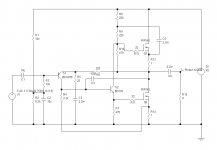
distortion seems pretty good (for simulation) at .02% at 20kHz and .007% at 1kHz.
Resistors R8 and R9 are very likely going to have to be variables (one or both) to adjust for Vt differences.
Concept is to use a fairly powerful FET (high current anyway) so that it operates in a linear region at a quiescent current of about 2A (depending on required output power etc. )
As with my earlier differentially driven 16W design, the voltage drive is split using equal load resistors R7, R10 which is about the only way to drive the FETs in equal and opposite directions.
Source resistors used to limit the current, otherwise I have kept this to 4 transistors as per the original.
There seems to have been some attempts to use MOSFETs in a JLH69 original.
Here is another. Some comments -
not exhaustively simulated, nor experimentally tried out yet.
distortion seems pretty good (for simulation) at .02% at 20kHz and .007% at 1kHz.
Resistors R8 and R9 are very likely going to have to be variables (one or both) to adjust for Vt differences.
Concept is to use a fairly powerful FET (high current anyway) so that it operates in a linear region at a quiescent current of about 2A (depending on required output power etc. )
As with my earlier differentially driven 16W design, the voltage drive is split using equal load resistors R7, R10 which is about the only way to drive the FETs in equal and opposite directions.
Source resistors used to limit the current, otherwise I have kept this to 4 transistors as per the original.
Attachments
the problem with mosfets is the about 4v gate to turn on.
you have 4 volts lost power supply overhead.
you have 4 volts lost power supply overhead.
Nigel, it's not a problem because the lower FET is driven from the PNP so the gate voltage only varies by about a volt or two, while the emitter is well clear at +15V.
The upper device is bootstrapped, so is also not a problem. I agree there would be a 4V limit if a current source had been used instead (plus the overhead of the current source) which is why I didn't.
However, in keeping things simple there is an asymmetry in the drive and it does show some near-clipping odd behaviour, which I suspect is because the FETs are not actually very linear, and the bootstrap is not ideal.
In the limit, the supply voltage has to be raised as Joachim mentioned.
The only way I got around this is to use driver transistors in front of the FETs and a proper CCS, but that would mean a more complicated circuit and a higher supply rail so as not to clip early.
That's the trouble with trying to keep to 4 transistors!
Last edited:
sorry i missed the bootstrapping.
i recently did a jlh 96 circuit with all recommended mods but used mj15003 transistors.
sounds really goo.
i recently did a jlh 96 circuit with all recommended mods but used mj15003 transistors.
sounds really goo.
However, there are a couple of edits I should make.
The problem I mentioned occurred because the centre rail wasn't centred properly, but the issue of asymmetrical conduction still occurs in this design, so premature clipping occurs before max theoretical output power is obtained.
It's more like a half-way house between a fully push-pull Class A and a resistor biased one.
Changes to improve the output power - lower input bias resistor 11k not 8.2k and R8 can be reduced to 100 ohms for higher output bias current.
As I implied, this is work in progress!

Nigel, it's not a problem because the lower FET is driven from the PNP so the gate voltage only varies by about a volt or two, while the emitter is well clear at +15V.
The upper device is bootstrapped, so is also not a problem. I agree there would be a 4V limit if a current source had been used instead (plus the overhead of the current source) which is why I didn't.
However, in keeping things simple there is an asymmetry in the drive and it does show some near-clipping odd behaviour, which I suspect is because the FETs are not actually very linear, and the bootstrap is not ideal.
In the limit, the supply voltage has to be raised as Joachim mentioned.
The only way I got around this is to use driver transistors in front of the FETs and a proper CCS, but that would mean a more complicated circuit and a higher supply rail so as not to clip early.
That's the trouble with trying to keep to 4 transistors!
You can try a decoupling capacitor in the gate of the lower MOSFET. As in the 60s. It will be easier to balance the load, stabilize the displacement, and introduce the local NBF.
You can build a class A floating bias circuit.
Heres the improved jlh96 circuit.
A general rule for a circuit to be stable is to make the dominant pole ten times more effective than any other pole. I don't see this arising with MJE340 in your critical Vas stage. A BD139 would be a far better choice.
Some time ago Nelson Pass did a MOSFET take on the JLH and called it the PLH. The article is on Nelson Pass' website.
Nigel,
Yes, I am fully aware of the improved 96 version. That was not my intention to provide an ultimate MOSFET version. As I mentioned, better symmetry between the FETS is possible with additional transistors, but I wanted to keep to 4.
For what it is worth, I'm not convinced by the improved circuit configuration. I prefer passive CCS's (i.e. base bias from an independent reference) rather than feedback current limits as they can be less stable (due to the local NFB). But, I'd certainly agree that a DC coupled output (no cap) would be superior and I have no doubt the overall performance is good.
I only proposed this as a simple amplifier to test whether MOSFETs can be used in the output in a variant of the original circuit. From the distortion characteristics it would seem possible.
I am also aware that Nelson Pass did a MOSFET version but I don't recall that having the same configuration as JLH's original.
Zero@Zone PCB
GZLOZONE J554 P-MOS FET JLH1969 klass A
MOSFET is attached instead of pnp Sanken 2SA1216 BJT 🙂
In the manual, setting the class AB. Quiescent current 30-70mA
Four transistors. At the exit MOSFET.
JLH 10 Watt class A amplifier #6638,6639,6640
GZLOZONE J554 P-MOS FET JLH1969 klass A
MOSFET is attached instead of pnp Sanken 2SA1216 BJT 🙂
In the manual, setting the class AB. Quiescent current 30-70mA
Four transistors. At the exit MOSFET.
JLH 10 Watt class A amplifier #6638,6639,6640
Last edited:
Description by J. Hiraga of the shown circuit http://www.dalixaudio.com/datasheets/A260.pdfYou can try a decoupling capacitor in the gate of the lower MOSFET. As in the 60s. It will be easier to balance the load, stabilize the displacement, and introduce the local NBF.
You can build a class A floating bias circuit.
Old DIY
I'm not seeking to significantly change or upgrade this circuit. The intention was to just try MOSFET outputs instead of BJT's. Yes, the behaviour is not ideal, but the circuit will deliver a low distortion (from simulation) at moderate power levels. The 1 ohm source resistors and 470 ohm gate resistors already provide a degree of LFB. What was a little surprising was that it was not enough with the bootstrap CCS but that is not ideal either. Nor was it in JLH's original design, but as also mentioned, the bootstrap provides significant drive to the upper device (in the original circuit) which gives it nearly ideal efficiency (provided OP transistors did not suffer quasi-saturation with a gain loss). With the 96 version a couple of volts is lost across the CCS, but that is not a major problem.
I'm not seeking to significantly change or upgrade this circuit. The intention was to just try MOSFET outputs instead of BJT's. Yes, the behaviour is not ideal, but the circuit will deliver a low distortion (from simulation) at moderate power levels. The 1 ohm source resistors and 470 ohm gate resistors already provide a degree of LFB. What was a little surprising was that it was not enough with the bootstrap CCS but that is not ideal either. Nor was it in JLH's original design, but as also mentioned, the bootstrap provides significant drive to the upper device (in the original circuit) which gives it nearly ideal efficiency (provided OP transistors did not suffer quasi-saturation with a gain loss). With the 96 version a couple of volts is lost across the CCS, but that is not a major problem.
Description by J. Hiraga of the shown circuit http://www.dalixaudio.com/datasheets/A260.pdf
Haha, I was looking at the schematic for a while, figuring out what is that odd thing... 🙂 It's clear now.. Never seen solid state amp with all 3 stages cap coupled til now... This one is John Curls nightmare circuit 😀
Update
The asymmetry seems to be worse if the quiescent current is too high.
By reducing the current the simulation showed a better balance! (1 to 1.2A for 10W)
This may be due to gain variation with current. Seems to be better the closer the current is to the ideal value for the Class A condition. As in the original 69 JLH, the lower FET can only get gate bias from the upper one reducing. So if there is a sweet spot where the gains are pretty linear over the current range that seems to be how the situation improves. Premature clipping (internally) not seen when power supply at 40V and driving 16W into 8 ohm load where Iq=1.5A.
I tried that long time ago... You could make it with mosfets, but I think that the thing with its sound signature is about loading (current modulation) of the phase splitter bjt, that you don't have with mosfets, except gate capacitances... I liked the bjt version better.Old DIY
I'm not seeking to significantly change or upgrade this circuit. The intention was to just try MOSFET outputs instead of BJT's. Yes, the behaviour is not ideal, but the circuit will deliver a low distortion (from simulation) at moderate power levels. The 1 ohm source resistors and 470 ohm gate resistors already provide a degree of LFB. What was a little surprising was that it was not enough with the bootstrap CCS but that is not ideal either. Nor was it in JLH's original design, but as also mentioned, the bootstrap provides significant drive to the upper device (in the original circuit) which gives it nearly ideal efficiency (provided OP transistors did not suffer quasi-saturation with a gain loss). With the 96 version a couple of volts is lost across the CCS, but that is not a major problem.
- Home
- Amplifiers
- Solid State
- JLH10W- MOSFET output