Note: This is more of a general question and not specific to a circuit, so there is no schematic.
Is there a point where there can be too much negative feedback in a stage?
My thinking is that if you had an ECC83 and used one half as a pre-amp stage feeding into the other half as a driver, but the pre-amp stage may have way too much gain for the driver stage to handle. I guess you could technically use a lot of negative feedback to really push it down, to save adding another physical tube, but what is the cost?
The alternative would be to use a lower gain tube for the pre-amp stage like a ECC82, and use reasonable values, but again would require another physical tube.
Any thoughts on this?
Last edited:
In tube stages that are not direct coupled, you can get peaking and/or instability at low frequencies,
due to coupling capacitors combined with excessive feedback in the stages. Normally global feedback
is used in a power amplifier, other than the usual cathode feedback from the cathode biasing resistors.
due to coupling capacitors combined with excessive feedback in the stages. Normally global feedback
is used in a power amplifier, other than the usual cathode feedback from the cathode biasing resistors.
Last edited:
Thank you rayma for the fast response.
so.. use the right tubes 🙂Normally global feedback
is used in a power amplifier
I was using the ole LED trick on both stages to keep the bias stable. Is this a bad idea in my situation?other than the usual cathode feedback from the cathode biasing resistors.
Sometimes fixed bias (which is what LED cathode bias is) allows too much variability.
Although LED bias usually results in higher gain, the local, direct-coupled feedback
of a cathode resistor will stabilize the operating point.
Although LED bias usually results in higher gain, the local, direct-coupled feedback
of a cathode resistor will stabilize the operating point.
Last edited:
Anything over 100% is too much in my opinion. 😀
I've experimented a lot with CCS-loaded pentodes with local feedback to bring gain down to ~10. The feedback is pretty heavy, but the results were great, very low distortion and the harmonics were low-order.
It is, however, certainly possible to implement the feedback poorly and get a bad result.
What you are proposing can be done well.
If you look at some of the newer McIntosh tube amps that are tweaked reissues of the old ones, they often have balanced inputs. If you look at the schematics, they will use half a 12AX7 as a grounded cathode amp with tons of feedback to get it to unity gain, then that is their phase inverter if you use unbalanced inputs.
I'm not a fan of this, but it's a practical application of the concept.
I'm not a fan of this, but it's a practical application of the concept.
Note: This is more of a general question and not specific to a circuit, so there is no schematic.
Is there a point where there can be too much negative feedback in a stage?
My thinking is that if you had an ECC83 and used one half as a pre-amp stage feeding into the other half as a driver, but the pre-amp stage may have way too much gain for the driver stage to handle. I guess you could technically use a lot of negative feedback to really push it down, to save adding another physical tube, but what is the cost?
The alternative would be to use a lower gain tube for the pre-amp stage like a ECC82, and use reasonable values, but again would require another physical tube.
Any thoughts on this?
If your goal is to kill off gain, you can use local feedback on the 1st stage. Because there is only one stage in the loop, there is very little phase shift and no danger of instability. The simplest way to do that is an un-bypassed cathode resistor, that will get your gain down fast. A cathode follower has 100% feedback and is quite stable.
If you wrap the feedback over two stages, there's more phase shift (each stage adds phase shift) so the chance for instability increases. But it all depends on the actual numbers. How much is the open loop gain and how much should the closed loop gain be?
Jan
I was using the ole LED trick on both stages to keep the bias stable. Is this a bad idea in my situation?
This is equivalent to a bypassed cathode resistor (the LEDs have a very low dynamic resistance), and it will not improve bias stability; in fact, for bias stability it is about as bad as you can get, as it provides no (DC) feedback. It also will do nothing to lower the gain.
Replace with a physical resistor and the gain drops and bias stability increases.
Jan
Sometimes fixed bias (which is what LED cathode bias is) allows too much variability.
Although LED bias usually results in higher gain, the local, direct-coupled feedback
of a cathode resistor will stabilize the operating point.
+1
You can only reduce the gain so much by simply increasing the cathode resistor, without also shifting the tube's operating point way "to the right" on its load line. At extremes, you can be operating the tube at very low currents where linearity is poor. Local degeneration mitigates this, of course, but it's better to operate the tube in its linear region instead of relying on local feedback to clean things up.
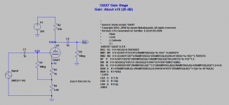
An effective approach to lowering stage gain without compromising its operating point is to split the cathode resistor into two resistors, as shown in the attached LTspice file. The load line plot for this stage is also provided. Resistor R3 establishes the bias for the stage and the gain is set by R2 and R4. To reduce gain, reduce R2 while increasing R4 such that the sum of R2 and R4 remains about the same (about 100k in this example). This will keep the operating point in about the same place while the gain is changed.
The only downside to this approach is that there will be a positive voltage on the grid so an input DC blocking capacitor is required. But that is a minor disadvantage, I think.
I hope this helps.
Attachments
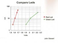
Example of LED Resistance at Some Currents
These are HP LEDs from the 80s. For the Red LEDS, if we take the diff between lines one & two the average resistance is 8.32R. Likewise the others lower down the list are 2.48R & 1.09R. That won't stabilize any common amplifier.🙂
These are HP LEDs from the 80s. For the Red LEDS, if we take the diff between lines one & two the average resistance is 8.32R. Likewise the others lower down the list are 2.48R & 1.09R. That won't stabilize any common amplifier.🙂
Attachments

If your goal is to kill off gain, you can use local feedback on the 1st stage. Because there is only one stage in the loop, there is very little phase shift and no danger of instability. The simplest way to do that is an un-bypassed cathode resistor, that will get your gain down fast. A cathode follower has 100% feedback and is quite stable.
One place where I can see needing to reduce the gain of the input stage is a Williamson amp with less global NFB, like a lot of people have tried. Of course the problem is that the input stage is also where the gNFB is applied. If you apply local NFB to that first stage, and then inject the gNFB to the cathode of that stage, you've got the two NFB loops working at cross purposes, right?
Or maybe that's a good idea? I don't know. That's why I'm asking...
Another place where local NFB could come in handy is an all-tube phono stage made with medium mu tubes (like two stages of 6DJ8 with a 6N6P on the output). As long as the RIAA filter is not in the grid circuit of the 6N6P output stage, you could adjust the gain and the output impedance of the whole preamp by changing the NFB around the output tube. The lower the gain the lower the output impedance, and vice versa.
--
I forgot to put in the previous post that I'm thinking of plate-to-grid local NFB (make the stage an 'anode follower'). That means you can lower the output impedance of the stage with local NFB.
Introducing local NFB by employing a large value, unbypassed cathode resistor (cathode degeneration) increases the output impedance if you take the plate as the output.
I was just playing around with the idea of an RIAA preamp with common cathode output stage, with plate-grid local NFB around the output stage only. Using three stages of 6DJ8 (ECC88) with plain old resistors as the plate loads, it looks like one could get 45dB gain with ease, without resorting to a high mu (and high input capacitance) tube like 12AX7 as the input stage. Or use a pentode as the output stage, with plate-grid NFB to adjust the gain.
Last edited:
Plate-to-grid feedback does decrease output impedance, but it also decreases input impedance. That isn't always a desirable thing.
Cathode degeneration does increase output impedance, as you say, by the feedback factor. But engineering is all about making compromises and there may be a time when controlling the stage gain is more important than the output impedance. It is good, though, to know what other impacts a particular circuit change will have. This would be a good example of that.
Alas, there is no "free lunch." 🙂
Plate-to-grid feedback does decrease output impedance, but it also decreases input impedance. That isn't always a desirable thing.
Only if it is parallel applied. If it is series applied, it will increase input impedance. There are two ways to apply negative voltage feedback.
A standard tube voltage amplifier stage doesn't lend itself easily to applying voltage feedback in series, but some use a p-channel fet follower in the cathode to do this, and it works quite well if you aren't totally averse to fet followers in your tube circuits.
Agree -- I was trying to keep things simple. 🙁
I suppose it's best to state the "general rules" with the disclaimer that special circuit configurations can invalidate these "rules." So here goes:
(1) sampling the output voltage reduces output impedance;
(2) sampling output current increases output impedance;
(3) applying feedback in shunt with the input reduces input impedance;
(4) applying feedback in series with the input increases input impedance.
The typical "anode follower" is an example of voltage/shunt feedback, whereas the circuit I showed is an example of current/series feedback. Both of these will reduce the gain of a single stage, but with different side effects.
Probably TMI, though. 🙂
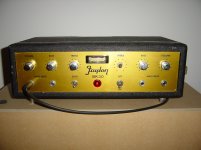
This Faylon BK30 guitar/instrument amplifier, of which I drew up the schematic, has feedback from plate to grid in the first stage of the two channels (and an ultra linear power stage).
A very quiet (noise/hiss-wise), and very nice sounding amp.
One mistake in the schematic though: The OPT is a Philips AD9047, the power transformer is a Craft 28TP4.
A very quiet (noise/hiss-wise), and very nice sounding amp.
One mistake in the schematic though: The OPT is a Philips AD9047, the power transformer is a Craft 28TP4.
Attachments

Last edited:
Agree -- I was trying to keep things simple. 🙁
I suppose it's best to state the "general rules" with the disclaimer that special circuit configurations can invalidate these "rules." So here goes:
(1) sampling the output voltage reduces output impedance;
(2) sampling output current increases output impedance;
(3) applying feedback in shunt with the input reduces input impedance;
(4) applying feedback in series with the input increases input impedance.
The typical "anode follower" is an example of voltage/shunt feedback, whereas the circuit I showed is an example of current/series feedback. Both of these will reduce the gain of a single stage, but with different side effects.
Probably TMI, though. 🙂
Excellent summary!
Perhaps a stupid suggestion due to my lack of technical expertise, but would a 7247 be a good alternative? It's a dissimilar dual triode with one 12AU7 section and one 12AX7 section, so no need for an additional tube.My thinking is that if you had an ECC83 and used one half as a pre-amp stage feeding into the other half as a driver, but the pre-amp stage may have way too much gain for the driver stage to handle. I guess you could technically use a lot of negative feedback to really push it down, to save adding another physical tube, but what is the cost?
The alternative would be to use a lower gain tube for the pre-amp stage like a ECC82, and use reasonable values, but again would require another physical tube.
Any thoughts on this?
The other thing I'm wondering about is that I've always been under the impression that the 12AX7 is not so good as a driver and that the 12AU7 is better. So if the 12AX7 has too much gain as an input tube and is a poor driver, why use it at all.
And if a 12AU7 would be an improvement over a 12AX7, might an even better choice be a 6CG7, 12BH7 or 6SN7?
- Home
- Amplifiers
- Tubes / Valves
- Too much local negative feedback?