Hi guys,
I am working on an idea of having a fully DC coupled design input driver stage / phase splitter.
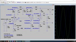
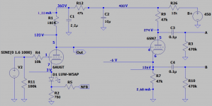
The idea is to use a 6AU6 in triode (I like that tube), DC coupled to the first section of 6SN7, that one DC coupled to the second section of that 6SN7 used as a classic phase splitter. I know cascading sections in DC coupled mode can be challenging, but that's all part of the fun.
On simulation, this works, quite well.
Any glaring mistake you guys see in this design?
I know the current in very low in all 3 tube sections an this could create problem, especially with the LED fixed bias component. If this become a problem, I can always come back to a classic cathode bias resistor.
Also I want to keep the splitter design.
Thank you
Brice.
I am working on an idea of having a fully DC coupled design input driver stage / phase splitter.
The idea is to use a 6AU6 in triode (I like that tube), DC coupled to the first section of 6SN7, that one DC coupled to the second section of that 6SN7 used as a classic phase splitter. I know cascading sections in DC coupled mode can be challenging, but that's all part of the fun.
On simulation, this works, quite well.
Any glaring mistake you guys see in this design?
I know the current in very low in all 3 tube sections an this could create problem, especially with the LED fixed bias component. If this become a problem, I can always come back to a classic cathode bias resistor.
Also I want to keep the splitter design.
Thank you
Brice.
Attachments

1. You need decoupling caps after each B+ dropping resistor.
2. I don't see a purpose for R13
3. You say on simulation this works quite well. What does that mean? What are the goals and how well does this circuit accomplish them?
In my experience the 6sn7 does not do its best at Vak=83V and Vg=-3.7V. Your sim should help you determine if the gain, distortion, etc. meets your goals and/or if it does that better than other configurations.
The goal of dc coupling can be accomplished in many ways. Level shifters, negative supplies, fewer stages, etc.
There's no decoupling on the B+ line between stages.
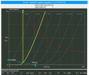
Looking at the curves for the 6SN7, in the second section of the 6SN7 there should be about 3.5 mA running at Vak = 100V and Vg1 = -4.6V, but in your simulation there is only 0,8 mA running.
What are you simulating it in?
Looking at the curves for the 6SN7, in the second section of the 6SN7 there should be about 3.5 mA running at Vak = 100V and Vg1 = -4.6V, but in your simulation there is only 0,8 mA running.
What are you simulating it in?
Thanks for the replies.
@dgta:
- I didn't add the decoupling caps just to keep the sim simple. I'll add them.
- R13 is a legacy and should be removed.
- I am getting a 50V peak swing at V(A) and V(B) @ 0.674% THD distortion, V(in) = 0.4 VAC
@PCL200:
- I use the latest LTSpice XVII
@dgta:
- I didn't add the decoupling caps just to keep the sim simple. I'll add them.
- R13 is a legacy and should be removed.
- I am getting a 50V peak swing at V(A) and V(B) @ 0.674% THD distortion, V(in) = 0.4 VAC
@PCL200:
- I use the latest LTSpice XVII
@Robert: I don't think so.
Yes, you're right. Time for me to sleep...
@Brice: Definitely add the caps. It doesn't matter for the dc run, but for the ac signals the bypass caps are shorts to ground.
OK, I was just puzzled about your first post in which you wrote that the circuit worked quite well in simulation. I would have thought that the circuit would have issues without the decoupling of the stages. But I have no experience with LTSpice at all.
Last edited:
Ok. I attached my sim file: you should try, LTSpice changed my life.
It is not 100% accurate, but very much close nonetheless.
It is not 100% accurate, but very much close nonetheless.
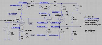
Brice, I ran your corrected file and here are my observations:
Your total gain is roughly 60 and distortion a little over 0.5%. I could not get more than about 20Vp at the output, inceasing the input past that point clips the second stage. This amount of gain and swing may be marginal or insufficient depending on what kind of final stage you use and how much GNFB.
Your first stage gain is roughly 36 and the gain for the second and third stages combined is less than 2. That's not ideal. You can do a lot better with a 6SN7.
If you're going to use the pentode in triode mode, use the triode symbol and model for that. The Ayumi model is 6AU6T (T for triode).
The LED I found listed as Vf=3.5V but in your circuit it only shows about half of that. I haven't looked into it, but I'm guessing you're not passing enough current to give you the Vf you want. For design purposes you can just put a voltage source in there and figure out the proper LED choice and biasing later.
Attachments
Thank you, I wasn't aware of the 6AU6T model.
What is the 6SN7wa you are using?
Yep, all the AF amp is the 6AU6's job. The first section of the 6SN7 isn't doing much. Maybe I should not use it all-together.
Agreed on the LED forward current. I might fallback to a cathode resistor but then I'll have to use a bypass cap which I could avoid with the LED.
Other than that, this seems to be a workable circuit.
@dgta: you are correct.
I would need a swing of 50V RMS to get the power side going.
Hum. That is not easy.
I would need a swing of 50V RMS to get the power side going.
Hum. That is not easy.
The 6SN7 model I use is the Wayne Clay model, I found it to be accurate.
The topology you chose is workable but you may not be able to easily get the performance you want/need out of it. Yes, you are correct. If your final (power) stage allows it, you could get rid of one section of the 6SN7. It's not doing much. There are many commercial designs that have only 2 stages, one high gain common cathode and one concertina. It depends on how much swing and gain you need.
If I can make a suggestion, the 6SN7 can be used as an LTP phase splitter, which can give you a substantial gain over what you have presently. I believe you can get a gain of as much as 7 to 8 with careful design. And more room for a larger swing. It also makes it a 2-stage circuit instead of 3 so dc coupling is less of a problem. Look up the Mullard 5-20 design and you'll see what I mean.
Edit: Also realize that 470k may not be a reasonable load for the circuit. Many power tubes in fixed bias require 100k or less grid to ground.
Last edited:
Thanks!
I'll look into the Wayne Clay model.
I wanted to stick with the concertina approach.
What if I introduce a negative supply to the design ?
I'll look into the Wayne Clay model.
I wanted to stick with the concertina approach.
What if I introduce a negative supply to the design ?
Sure, you can add a negative supply or, if you already need a negative supply for biasing the power tubes, you can tap into tat.
Yes I do have a bias supply, but I'll have to think how to do that.
I've tried to remove one 6SN7 section, just for fun.
It is much easier with only 2 tubes.
I can have a much higher input level, 1.4V and I don't clip anymore the driver stage. That way I can reach 30V swing, not bad but not great either.
I've tried to remove one 6SN7 section, just for fun.
It is much easier with only 2 tubes.
I can have a much higher input level, 1.4V and I don't clip anymore the driver stage. That way I can reach 30V swing, not bad but not great either.
Attachments
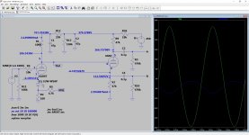
With little changes I think you get over 50V swing.That way I can reach 30V swing, not bad but not great either.
Mona
Attachments
- Home
- Amplifiers
- Tubes / Valves
- DC coupled driver/spliter prototype: will this work?