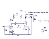
I have an SE D3a driver setup that seems to work pretty well in simulation. I need to swing the grid of the D3a to within .2 volts of 0 to clip the output tube though. Anybody have experience running them like that? Are grid current problems likely?
The basic setup is resistor loaded cathode biased 180V A-K @ 18mA with the heater biased up to +50
Thanks,
Marty
The basic setup is resistor loaded cathode biased 180V A-K @ 18mA with the heater biased up to +50
Thanks,
Marty
What's driving the grid of the D3A? I would adjust the operating point to get yourself a little wiggle room.
I have an SE D3a driver setup that seems to work pretty well in simulation. I need to swing the grid of the D3a to within .2 volts of 0 to clip the output tube though. Anybody have experience running them like that? Are grid current problems likely?
The basic setup is resistor loaded cathode biased 180V A-K @ 18mA with the heater biased up to +50
Thanks,
Marty
Grid current through grid leak resistor will shift bias further positive. Extent of such will depend on value of grid resistor. What is value of grid resistor?. I bias D3a at -0.3V with Rg 39R, 10mA 60V with no problem, but Rg value is the key.
I built a jig to measure grid current, type 6688/E180F was consistently lower (about half from memory) and much more consistent between samples. Same pin-out, similar enough that you might try it (much cheaper and they sound good too).
Last edited:
Thanks for the replies, I'm looking at it for a combined input/driver stage so something reasonably high for Rg is required. The only way I see to lower R in the grid circuit would be to add an input transformer to keep the ac load reasonable but that still gets somewhere around 1K Rgk. An alternative to get some more wiggle room would be an active load but then I think the advantages over a medium mu srpp stage start to disappear.
Got a schematic, SRPP (why)?.
Here is a schematic of the headphone amplifier I am working on with the D3a inserted. The 45 in the schematic is standing in for a VT52 as I don’t have a model and Cin, u and Ra are close enough. The output stage parts along with the regulators are in hand or on the way. This was kind of an 11th hour rethink of the input stage based on the tubes and parts I have laying around. the D3a is shown with a large cathode bypass cap which gets me about .86 volts of headroom on the grid for full output. Comparing this to the srpp stage from the original wavelength bugle 45 (link below), the srpp has better distortion performance whereas the D3a with the local degeneration is better in this respect but then headroom is tough. Since I don’t really need the extra drive current in this case, it might just be better to stick with the srpp.
https://www.wavelengthaudio.com/bugle.pdf

Last edited:
If you loaded the D3A with a plate choke, cathode bias voltage could be brought up significantly.
If you loaded the D3A with a plate choke, cathode bias voltage could be brought up significantly.
I actually have plate chokes on hand and tried that in the simulation. There is plenty of headroom at that point but still RK needs a large bypass to get reasonable bandwidth. Perhaps diode bias would work without the bypass but there is still greater distortion than the srpp without degeneration and the issue of the chokes picking up noise would need to be dealt with. I think those trade-offs make sense if I needed the drive current but in this case maybe not.
People were quite happy with the performance of the 6072A SRPP in that amplifier.
About the only thing I have further to offer is that (did you say this was a headphone amplifier?), when the headphone is playing as loud as you are likely to listen, how much swing is there at the D3a grid?.. you might not need full output from the 45.
Cheers.
About the only thing I have further to offer is that (did you say this was a headphone amplifier?), when the headphone is playing as loud as you are likely to listen, how much swing is there at the D3a grid?.. you might not need full output from the 45.
Cheers.
I use transformer input (1:1 for nominal 600 ohm balanced signalling) with D3A and in one application cascode mosfet based CCS/follower (hybrid mu-follower) in the GM70 I use IT transformers and fixed bias with input transformers.
Plate current in the 15 - 20mA range and plate voltages in the range of 190 - 220V.
In CCS applications the supply feeding the CCS is 400V so I can swing at more than 200Vpp without linearity issues. It can operate into the grid current region because the sources are capable of delivering substantial current. (I've never seen more than 100uA or so) In normal listening situations this will never happen.
The D3A has very steep transconductance slope and I have designed my driver circuits to accommodate wide variations in tubes.
- Home
- Amplifiers
- Tubes / Valves
- Quick question D3a Triode