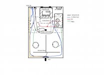
Hello, I've finished making Chiomenti's "Lo scherzo" whit ECL82 tubes and I must say that it plays OK, even though I don't have very efficient speakers. However, I noticed that in one channel, precisely that relating to the O.T. on the right (see diagram), it was initially buzzing. The problem is that at first I was running the 8Ohm output through the wire just behind the power transformer.
Now, I ran it around the case like the diagram. The buzz has decisely decreased but it is always slightly higher than the other channel. Moreover I have the perception that it is a little bit louder (tried with listening in headphones because I did not feel it with the speakers).
Any suggestion for this?
Forthermore, since I wish to use it also like an headphone amp because low wattage, what kind of adapter could I think of for proper running? Thanks.
Attachments
Google says it's this:
Is the hum 50Hz or 100Hz? If it's 50Hz, it's probably magnetically coupled or bad signal grounding. If it's 100Hz, it's probably bad power grounding. If you short the input, does it go away? If not, take the power transformer and move it away from the chassis (using some kind of extension cord). Does the hum go away? The fact it's louder on one side seems to point to something magnetic since it's on the "power supply" side of the amp.
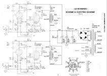
EDIT: is the cathode resistor on the pentode really 1k2? Seems awfully high as this results in only 20mA flowing... maybe 1k2 and 1k5 in parallel for different power settings like low and high? I didn't find the article, just this schematic 🙂
Is the hum 50Hz or 100Hz? If it's 50Hz, it's probably magnetically coupled or bad signal grounding. If it's 100Hz, it's probably bad power grounding. If you short the input, does it go away? If not, take the power transformer and move it away from the chassis (using some kind of extension cord). Does the hum go away? The fact it's louder on one side seems to point to something magnetic since it's on the "power supply" side of the amp.
EDIT: is the cathode resistor on the pentode really 1k2? Seems awfully high as this results in only 20mA flowing... maybe 1k2 and 1k5 in parallel for different power settings like low and high? I didn't find the article, just this schematic 🙂
Attachments
Last edited:
In effect I guessed it was a sort of magnetic coupling with the transformet, in fact when it is away from the amplifier (5-10cm) hum/buzz is almost inaudible from both channels. I don't think it's a ground loop or similar because I took care on paths, rather could be a bad matched tube pair? They are General Electric bought together as NOS, but I didn't measured their values.
Now I'm running it in triode mode (I know it's possible to swap into pentode but I should use a DPDT switch and I don't intend at present). I report the schematic I followed.
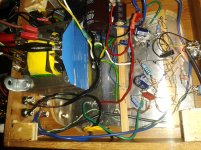
Yes it may be helpful a photo, so soon as possible I'll post one of the interior.
Now I'm running it in triode mode (I know it's possible to swap into pentode but I should use a DPDT switch and I don't intend at present). I report the schematic I followed.
Yes it may be helpful a photo, so soon as possible I'll post one of the interior.
Attachments

I have no way of knowing if this causes (part) of your problem, but I don't think that it is wise to twist the two leads that are running from the speaker terminals to the switch for NFB you made next to the volume pot.
Twisting is mostly done to lower magnetig radiation (like in ac filament leads, like you did in your amplifier). But you don't want to 'cancel' anything between the left and right channel. I think it is better is to use two seperate shielded wires for these connections.
Is it possible to post a photo that's a little bit sharper?
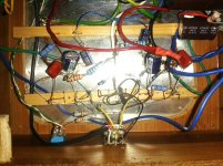
I hope these ones are clearer (sorry but I make them with cellphone).
As for the feedback wire, yes it's five cm about from potentiometer. If I understood well you suggest something like a coaxial cable...thanks for the tip, where should I link the shielding then?
As for the feedback wire, yes it's five cm about from potentiometer. If I understood well you suggest something like a coaxial cable...thanks for the tip, where should I link the shielding then?
Attachments
Did you try the things kodabmx suggested?
From the diagram in your first post I understand that you added a filter choke (instead of R21, the 470 Ohm resistor?). In line with the advise of kodabmx, you could try to temporarily disconnect the choke and replace it by a resistor of about the same value as the dc-resistance of the filter choke. In this way you will know whether the choke is causing magnetic coupling or not.
Are you aware of the rules for placing transformers/inductors relative to eachother so to minimize the chance on magnetic/inductive coupling between them? Could you post a photo of the topside of your amplifier?
Last edited:
In addition (or correction...): If the dc-resistance of your filter choke is relatively low, than temporarily replacing it with a low value resistor can introduce hum (100Hz) itself, because the filtering of the choke (if it has normal value, like 4 H or higher) will be far better than with the resistor.
What is the dc-resistance of your choke? And it's value for H?
What is the dc-resistance of your choke? And it's value for H?
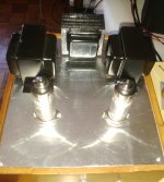
Yes, the filter is just as you said a CLC with the choke of 2.5H (R is around 50 Ohm). You can see it in the in the middle of the picture of the top side.
You can notice I oriented the OT at 90° respect to the inductance, and the transformer laying at bottom perpendicularly with the aluminium sheet.
You can notice I oriented the OT at 90° respect to the inductance, and the transformer laying at bottom perpendicularly with the aluminium sheet.
Attachments
Last edited:
The orientation on the topside looks fine to me. The power transformer also looks to be orientated ok, but is pretty close to the three on the topside.
Try disconnecting the choke and replace it temporarely with a resistor of 220 Ohm (at least 2 Watt) or even some more, up to 470 Ohm (at least 3 W).
With 220 Ohm your B+ will be some 9 volts lower, with 470 Ohm some 20 volts lower. But looking at your measurements at the cathodes of the pentode sections, I think your B+ must be a bit higher than the 285 V (or the 275 V at the anode) in the schematic anyway, so for trying out, the somewhat lower B+ is no problem.
You did ground the heater winding of the power transformer (at only one place), or?
Last edited:
The orientation on the topside looks fine to me. The power transformer also looks to be orientated ok, but is pretty close to the three on the topside.
Try disconnecting the choke and replace it temporarely with a resistor of 220 Ohm (at least 2 Watt) or even some more, up to 470 Ohm (at least 3 W).
With 220 Ohm your B+ will be some 9 volts lower, with 470 Ohm some 20 volts lower. But looking at your measurements at the cathodes of the pentode sections, I think your B+ must be a bit higher than the 285 V (or the 275 V at the anode) in the schematic anyway, so for trying out, the somewhat lower B+ is no problem.
You did ground the heater winding of the power transformer (at only one place), or?
About your last question, yes it's a 3.15-0-3.15 so the heaters connection is grounded.
Thanks. I'll try and see how you reccomend...I think 10V or lower on B+ should not affect so much. Now it runs at 285V just before the pentode plate and 240 at first section plate.
- Home
- Amplifiers
- Tubes / Valves
- ECL82 amplifier question