Hi,
I recently completed an Aleph J build and it sounds great and is stable. But one issue I've noticed is that when I measure the bias over the source resistors on each channel, they are not even.
For example, the source resistors on the right channel are at .38V and .42V.
The difference on the left is slightly larger at .36 and .43V.
I used matched MOSFETS from a reliable source.
Any ideas on the cause or whether this is something to worry about? Where would you set the bias given that they are not even?
Any thoughts are greatly appreciated.
if there is no load on output while you're measuring that, and resistors are of same value, there are only two possible explanations :
- source resistors are not actually equal in value ( one is erring 5% down, while other 5% up and that's it)
- bad battery in your DVM
for better sleep , you can change them , and it'll probably sound better ( depends of many things -efficiency and/or sensitivity of your speakers, your ears and your personal taste)
if going to measure them , measure them in best way - use small CCS and measure voltage drop on them ; best is to ( negating need for repetitive accuracy) solder them in series, push said current through chain , and then measure in one fly each of them
Last edited:
For example, the source resistors on the right channel are at .38V and .42V. The difference on the left is slightly larger at .36 and .43V.
I used matched MOSFETS from a reliable source.
Perhaps the heat sink is not the same temperature for the two transistors.
I wouldn't get too excited in any case.

Two other possibilities
1) If you're using crappy silicone thermal pads, and the torque applied to the bolts is different this can lead to different die temperatures which will affect current draw at constant Vgs. I have measured and observed this
Make sure your mosfets are tightly mounted preferably with spring washers.
2) Is it possible you have 2 x quad matched mosfets, and not 1 x oct matched, and you have randomly selected them thinking that all 8 were matched?
premise is that rails are equal and DC offset is 0/ no load on output
if that is not the case, everything is possible 🙂
if that is not the case, everything is possible 🙂
I've told you , and just in case - take in account remarks from two esteemed Gents - check mosfet thermal arrangement (heatsink flatness, torque)
after that - either chill, or match new set of resistors , no big deal either way
edit: frankly - I was eluded with my version of Papa's J - having just a pair of IRFP150 per channel , which is simpler
so , now - in case of pair down and pair up , to avoid any misunderstanding - best to write it down clearly , for each channel - voltages across each of 4 source resistors
upload ref. schematic and follow parts nomenclature , or make little sketch with source resistors and voltages on them
in any case , if you're in 10% bracket, whatever value spread arrangement you have, you're mostly good
Last edited:
Per your initial post, I have ordered some 1% 3W wirewound resistors. Pricey, but we'll see if they make a difference.
I am also checking the heat sink connections and the screw tightness on the Mosfets. That definitely could be a factor because I drilled my own holes and was worried about over-tightening and puncturing the silicon pads.
But I am not going to put too much effort into it because it already sounds great. I will report back.,
Then use spring washers.
This will ensure that you get fairly reasonable compressive load on the mosfet without fear of damaging anything.
Run a thermal cycle then recheck all bolts are still tight.
This will ensure that you get fairly reasonable compressive load on the mosfet without fear of damaging anything.
Run a thermal cycle then recheck all bolts are still tight.
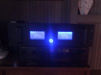
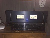
As an aside, I added Weston VU meters to my Aleph J from a Quad Eight console and some blue LEDs to match the power button.
You'll see in the photos that it is currently resting on a much old Nelson Pass design that I've been using in my beach house for years.
You'll see in the photos that it is currently resting on a much old Nelson Pass design that I've been using in my beach house for years.
Attachments
I used matched MOSFETS from a reliable source.
And how do you know they are matched? How well are they matched? FETs of all types have such large variations of Vgs I would have my doubts.
- Home
- Amplifiers
- Pass Labs
- Aleph J with uneven bias across source resistors