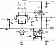
My headphone amp is the ''All-Fet Line Amp'' EB-107/309 + ''All-FET Low Noise Regs'' EB-704/418, all dual mono with CRC filter before the Regs... According to the Line amp documentation it can drives 30 ohms in Class-A, enough for an headphone amplifier 😉 As per the doc I added a 10ohms resistor in series with the output.
Volume pot is a Noble AP25.
SB
Volume pot is a Noble AP25.
SB
Also fitted is a buffered Danyuk crossfeed in balanced mode with volume control.
.
Hi,
Would you have reference to the circuit you used?
I have Dimitri Danyuk's Electronics World August 2005 article but that is 'fully' variable.
Hi Patrick,
I managed to find the F5-HA document but I would never have found the simulation schematic/files that you referred.
Thank you very much.
I managed to find the F5-HA document but I would never have found the simulation schematic/files that you referred.
Thank you very much.
See also :
http://www.linearsystems.com/lsdata/others/Headphone_Amplifier_Evaluation_Board.pdf
Ref 4,5.
Patrick
http://www.linearsystems.com/lsdata/others/Headphone_Amplifier_Evaluation_Board.pdf
Ref 4,5.
Patrick
There is a discussion in the Pass forum J2 thread about the MCS version discussed here in post #5.
You can easily turn this into a power amp by changing the MOSFETs to 2SJ618.
And change R10 to 0R47, R13a to 0R24, and R13b to 0R26, using 20~24V rails.
Bias will be around 1.2A.
All components are acrively available, no unobtaniums required.
And it will have a very similar signature to the J2, dominanted by H2.
Cheers,
Patrick
See also :
http://www.linearsystems.com/lsdata/others/Headphone_Amplifier_Evaluation_Board.pdf
Ref 4,5.
Patrick
I looked at that schema from linear systems. I have no clue how it works - the input drain references to a LED - that is, AC zero ohms, so no amplification - and goes to the gate of the next stage (Q102/Q112);
while the inverted pair does see 270 ohms in the drain so there is amplification there but it goes to the source of the next stage (again Q102/Q112);
unless the next stage pair (Q102/Q112) is in fact wired as a cascoded pair.
And there is a high impedance DC feedback to the same next stage via the sources of (Q102/Q112).
Not really fit for 32 ohms Fostex Planar that are on my list, I'm afraid . .
The only thing that circuit has to do with this thread is the passive crossfeed circuit.
You should PM the designer himself (DIYA member Dimitri) if you have issues to address with that design.
The EB602 will drive 32 ohm with ease.
Cheers,
Patrick
You should PM the designer himself (DIYA member Dimitri) if you have issues to address with that design.
The EB602 will drive 32 ohm with ease.
Cheers,
Patrick
edit: Have revisited this, it seems the conceptual schema is just like the HAGS this thread is about. There it looks more simple.
Now I do think I understand & it is like I supposed.
Now I do think I understand & it is like I supposed.
I can only change the content of Post#1, not the title.
Apologies for the typing mistake,
Patrick
Apologies for the typing mistake,
Patrick
Adding a 4-transistor Wilson Mirror
In EUVL's document about this project, Post #2, he mentions, and I'm paraphrasing here:
The use of a 4-transistor Wilson mirror will not only reduce distortion, but will also improve DC offset.
I am very, very close to convincing myself to give this project a try and improved DC offset is of particular interest to me. Google shows a number of 4-transistor mirrors, but I cannot envision how to adapt them to this particular circuit.
If anybody would like to help, I would be thankful for a quick sketch showing the addition of a 4-transistor Wilson Mirror to this circuit.
- Home
- Amplifiers
- Headphone Systems
- The Borbely EB602-200 Revisited
 done
done 