Why do i need to repeat to you what i already told sotomano? I was talking about dadog's BSA amp which is -90db thd, the same with the other VFA amps...
Why do i need to repeat to you what i already told sotomano? I was talking about dadog's BSA amp which is -90db thd, the same with the other VFA amps...
Of course using VFA can have low distortion also, but using CFA is easier to get higher slew rate.
I doubt any amplifier at 80's can have distortion 0.003% at 20kHz. If distortion 0.003% at 1kHz, I believe it. 20 year ago, I design an amplifier that have distortion 0.003% at 1kHz, 100W rms, 8.2 Ohm dummy load. At that time, I do not use simulation and I do not know Bob Cordell who advocate to get low distortion at 20kHz. So, I do not measure distortion at 20kHz.
Instead of senseless bickering, I would like throw in another interesting measurement, which is somehow related to Mauro Penasa's work.
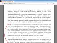
Pavel measured the distortion of the voltage at the speaker terminals and the distortion across an 1 Ohm resistor in series, in the same setup.
It is interesting, how nonlinear the speaker behaves and imposes it's nonlinearity on the current.
Current drive of speakers and speaker distortion
How would that measurement look, if the 1 Ohm resistor would be reduced to 0.1 Ohm?
Problem is that current drive and GNFB are too completely different subjects. Trying to mix them will end in confusion on an already confused thread!
It's misleading to look at the current distortion, it's the speaker distortion that matters.How would that measurement look, if the 1 Ohm resistor would be reduced to 0.1 Ohm?
A 1 Ohm resistor is very comparable with a speaker's own impedance which means it will significantly affect any measurements. A much lower resistance should be used like 0.1 Ohm or even lower.sottomano said:Pavel measured the distortion of the voltage at the speaker terminals and the distortion across an 1 Ohm resistor in series, in the same setup.
The same idea is used in using a galvanometer to convert it into an ammeter. The galvanometer is connected across a very low shunt resistance not to disrupt any circuit in which it is inserted.
In a way, a speaker is a loaded linear electric motor. It has inductance, resistance and capacitance. Simply adding a 1 Ohm resistance in series and expecting the entire circuit to behave as if nothing changed without taking into consideration of the electronic parameters of the output and loadspeaker, is not correct.
I humbly would say, using a very high quality microphone in front of the speaker to compare the output from the microphone and output into the speaker, can yield more objective results.
Last edited:
That measurement per se doesn't have to do with current drive. But it shows that the current gets distorted by the speaker.Problem is that current drive and GNFB are too completely different subjects. Trying to mix them will end in confusion on an already confused thread!
I's say if we use 0.1 Ohms, the distortion is even bigger.
It's misleading to look at the current distortion, it's the speaker distortion that matters.
OK, and how do voice coil movement and current relate?
A 1 Ohm resistor is very comparable with a speaker's own impedance which means it will significantly affect any measurements. A much lower resistance should be used like 0.1 Ohm or even lower.
[...]
In a way, a speaker is a loaded linear electric motor. It has inductance, resistance and capacitance. Simply adding a 1 Ohm resistance in series and expecting the entire circuit to behave as if nothing changed without taking into consideration of the electronic parameters of the output and loadspeaker, is not correct.[...]
I would say, if you use a lower resistance, that distortion would even increase, because the source of that added distortion is the loudspeaker, and if you give it less reistance, it increases....
Well, but there is not much reason to believe that these distortions do not somehow show up at the voice coil (independently of the fact whether they have been originated by the coil itself or by something else...)It depends on the speaker
ExactlyI humbly would say, using a very high quality microphone in front of the speaker to compare the output from the microphone and output into the speaker, can yield more objective results.
don't derail the discussion. I'm really interested in looking at it from the electrical side. Any other opinions?
Of course using VFA can have low distortion also, but using CFA is easier to get higher slew rate.
I doubt any amplifier at 80's can have distortion 0.003% at 20kHz. If distortion 0.003% at 1kHz, I believe it. 20 year ago, I design an amplifier that have distortion 0.003% at 1kHz, 100W rms, 8.2 Ohm dummy load. At that time, I do not use simulation and I do not know Bob Cordell who advocate to get low distortion at 20kHz. So, I do not measure distortion at 20kHz.
Well...dadog's amplifier shows -90db thd at 1khz not 20khz, but i can show you some amps from the 80's that have less than 0.003% thd in all audio range and even 0.0005 % at 1khz .
I shouldn't tell you that yet , but i already told others for years so now you get informed too: they are designed by the same guys who made ACCUPHASE, yet they are all Voltage Feedback designs.
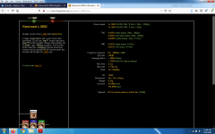
Here's the review for the lower end of that L-series, the only one that got to Europe and USA, all the L series was sold in Japan only.
Kenwood KA-1000 Integrated Amplifier Review price specs - Hi-Fi Classic
There are many other amplifiers from yamaha or marantz that were the best possible quality, but never got world wide recognition as they were sold only in Japan.It's now with the internet that we get to know them...There was no internet in the 80's....but don't take the word of a "technician" on that. The Internet might have been an underground movement in the 80's as well 😉
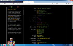
And a Fisher from 1981(0.002% THD) i found a few months ago, very simillar to the KA-1000 too:
Fisher BA-6000 Stereo Power Amplifier Manual | HiFi Engine
None of them are symmetrical or current feedback.
Attachments

Last edited:
http://www.cieri.net/Documenti/Kenwood/Documenti tecnici/Kenwood - Sigma-Drive Technical Guide.pdfdon't derail the discussion. I'm really interested in looking at it from the electrical side. Any other opinions?
A driver can be operated on any source impedance from -Re via 0R to +infinity. -R is full motional velocity feedback in the driver, 0R is standard voltage drive and +infinity is pure current drive. With any source impedance we can pre-EQ the driver's SPL to flat (or whatever reasonable target), or better yet, EQ the terminal voltage to the target that gives the desired SPL curve.don't derail the discussion. I'm really interested in looking at it from the electrical side. Any other opinions?
To first order, this will sound and measure, acoustically, the same regardless of source impedance, by sheer definition. But the fine print will be different, for example harmonic distortion and excursion overload recovery.
We can measure electrical distortion for both driver terminal voltage and current independantly. Obviously, when impressing voltage (0R) voltage disortion is zero (residual of amp) and when impressing current, current distortion is zero. With any other source impedance we will see both current and voltage distortion. The hard part is correlate that to measured acoustical distortion and any other non-LTI effects. It may turn out that for a given driver in a given acoustic loading, a varying source impedance profile vs. frequency obtains best results overall.
For the amp, of course the "drive mode" may also result in different residual distortion and that may add to the fine print if the amp distortion is significant, and with more subtle things like output impedance not being stable (changing with large signal, drifting thermally via bias, etc).
... crest factor reduction ...
Can you explain how that figures in an amp design? Crest factor as I know it, is the ratio of the peaks in the signal to the average level of the signal. It is not a circuit property, unless I missed something?
Jan
Crest_factor
I think the idea is that circuit distortion can change the crest factor. In an undistorted sine wave the peak to RMS (not average) is 1.4.
Thank you KSTR for sticking to the very question. So, as I thought, this confirms that lowering the measurement resistor (and thus the effective source impedance) would increase measured current distortion.[...]
We can measure electrical distortion for both driver terminal voltage and current independantly. Obviously, when impressing voltage (0R) voltage disortion is zero (residual of amp) and when impressing current, current distortion is zero. With any other source impedance we will see both current and voltage distortion. The hard part is correlate that to measured acoustical distortion and any other non-LTI effects. It may turn out that for a given driver in a given acoustic loading, a varying source impedance profile vs. frequency obtains best results overall.
[...]
Of course, speakers are supposed/designed to be driven by a voltage source (Z amplifier << Z Loudspeaker), if not they will not produce a flat Frequency Response.
However, as far as I know it is ultimately the current that drives the motor.
Also, I do not suppose that the crossover components (Inductors, caps and resistors) will contribute substantially to that current distortion.
Therefore, there must be some nonlinearities in the loudspeaker motor or it's loading to produce these distortions.
Closing the loop (sic) and coming back to the feedback and, correlated, output Z topic of an amp, it doesn't seem to me that an as
high as possible damping factor (0R drive) will be the best thing, as it doesn't pose any resistance to those speaker induced nonlinearities.
So maybe there is a sweet spot between ultra low output Z and the issues a highish (say 0.5 Ohms) Z produce (FR deviations). Of course dependant of the loudspeaker, but it's not that usual commercial speakers are that different.
Are you hypothesizing that the electrical non-linearity of a speaker is affected by the resistance between its terminals?So maybe there is a sweet spot between ultra low output Z and the issues a highish (say 0.5 Ohms) Z produce (FR deviations). Of course dependant of the loudspeaker, but it's not that usual commercial speakers are that different.
- Home
- Amplifiers
- Solid State
- Global Feedback - A huge benefit for audio