What about distortion vs frequency in audio range?
Most 0.000X % distortion opamps as most amplifiers have rise in distortion above 1KHz or so, no matter what is distortion percent.
Why "nobody" cares about that?
Most 0.000X % distortion opamps as most amplifiers have rise in distortion above 1KHz or so, no matter what is distortion percent.
Why "nobody" cares about that?
What point are you trying to make? Or are you just running through the playbook for discussions on negative feedback and this is the next one on the list?
What point are you trying to make? Or are you just running through the playbook for discussions on negative feedback and this is the next one on the list?
Yes, I think you're clairvoyant.

What about distortion vs frequency in audio range?
Most 0.000X % distortion opamps as most amplifiers have rise in distortion above 1KHz or so, no matter what is distortion percent.
Why "nobody" cares about that?
It's not hard to make a no feedback amp do this, MOSFET output with large capacitive input loading the previous stage. It's even in quadrature with the input an evil twin of PIM, etc. Why again was this thread resurrected?
I'm not sure. I think it's so people can obfuscate and generally pretend to be in possession of great audio wisdom and mystery.
generally pretend to be in possession of great audio wisdom and mystery
I apologize, I just noticed that I had promised the OP that I would not post in his threads so I will back out now.
It's not hard to make a no feedback amp do this, MOSFET output with large capacitive input loading the previous stage. It's even in quadrature with the input an evil twin of PIM, etc. Why again was this thread resurrected?
😕 I was thinking about amps with gnfb that have rise of distortion with frequency.
I KNOW it's been debated in several blowtorch, Cordell threads but they're gigantic and It's hard to search that...looks like it's heresy to ask.
I apologize, I just noticed that I had promised the OP that I would not posts in his threads so I will back out now.
So did I many years ago, I didn't notice who the OP was before I did some post in his thread.
In one of the Krill discussions, we came to an agreement that I should not make any comments in his threads or at his posts and vice versa.
Jason negotiated this agreement.
This is my last post in this thread.
Stein
😕 I was thinking about amps with gnfb that have rise of distortion with frequency.
Everyone knows this. Loop gain decreases with increasing frequency. The vast majority of feedback amplifiers are dependent on loop gain to reduce distortion. A carefully designed feedback amplifier will mitigate this, just like a well designed "open loop" amplifier will mitigate this phenomena.
😕 I was thinking about amps with gnfb that have rise of distortion with frequency.
I KNOW it's been debated in several blowtorch, Cordell threads but they're gigantic and It's hard to search that...looks like it's heresy to ask.
It is because non linearity of internal capacitance of transistor and very low loop gain at high frequency. If you use simple miller compensation on simple circuit, of course you have distortion rise with frequency after around 1kHz.
You can reduce high frequency distortion with high loop gain until 20kHz or/and make minimum influence of internal capacitance of transistor using cascode or bootstrap, or/and choose very low internal capacitance of transistors, etc.
Cascodes need compensation themselves, but generally this poles compensation finds an equivalent in another expression that annoyed engineers because it makes easier to be understood by simple technicians with not so deep theoretical knowledge(like me) which is " slowing down the circuit's slew rate" or a more modern term which is " crest factor reduction" that directly relates with the powers of harmonics, because distortions aren't just a qualitative term, but also and mainly a quantitative term or what energy is drawn or taken away from a pure sinus waveform through nonlinear amplification. .
That so called "simple miller " compensation is in essence the same thing as compensating a cascode , it is just that it's usually one order of magnitude higher, so a cascode will improve both speed and distortions by 10 times.It should improve speed and distortions following a quadratic function, but it cannot be made to work like that in real audio circuits due to pcb and physical distancing between components constraints.
If you need to compensate a simple transistor you may need 33pf while compensating a cascode you'll need only 3pf to get it stable enough with normal pcb constraints.
Having two compensated cascodes one after another will theoretically give two order of magnitude improvement in both distortions and speed although you need aditional measures to slow the amp's speed even more because it cannot be too high with the normal pcb constraints and here's impedace matching coming into action with its own downsides.
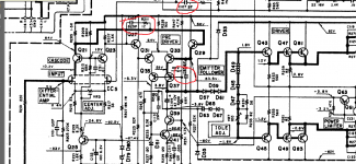
Audio components aren't constructed the same ways as fast radio or video components so the pcb itself will deconstruct the compensation, thus you need to slow down (or compensate) the circuit a little bit more than theoretically possible so two cascodes one after another will not automatically give you 100x lower distortions without a very well designed PCB around its components and electrical impedance matching. If you look in both schematics i shown here you can see there's also an impedance matching stage between the transconductance stage and VAS stage and that is exactly to be able to preserve the slew rate of the input stage , but the impedance matching stage needs its own compensation, thus it will aditionally slow down the whole circuit!!!
Radio transitors can be built internally as cascodes in 1 square mm or even smaller so they can be used in a different way than normal audio components , thus you cannot and should not use audio components the same way as radio components with the simple wish of making it faster and faster .
I mentioned a term which is rarely mentioned unfortunately, which is the Crest factor. This is actually a very good unifying term that can make people understand more the source of distortions in power supply, digital realm and analogue realm all together.For this i am going to point out just a simple article that can bring some joy to you:
Harmonic distortion indicators - Crest factor - Electrical Installation Guide
That so called "simple miller " compensation is in essence the same thing as compensating a cascode , it is just that it's usually one order of magnitude higher, so a cascode will improve both speed and distortions by 10 times.It should improve speed and distortions following a quadratic function, but it cannot be made to work like that in real audio circuits due to pcb and physical distancing between components constraints.
If you need to compensate a simple transistor you may need 33pf while compensating a cascode you'll need only 3pf to get it stable enough with normal pcb constraints.
Having two compensated cascodes one after another will theoretically give two order of magnitude improvement in both distortions and speed although you need aditional measures to slow the amp's speed even more because it cannot be too high with the normal pcb constraints and here's impedace matching coming into action with its own downsides.
Audio components aren't constructed the same ways as fast radio or video components so the pcb itself will deconstruct the compensation, thus you need to slow down (or compensate) the circuit a little bit more than theoretically possible so two cascodes one after another will not automatically give you 100x lower distortions without a very well designed PCB around its components and electrical impedance matching. If you look in both schematics i shown here you can see there's also an impedance matching stage between the transconductance stage and VAS stage and that is exactly to be able to preserve the slew rate of the input stage , but the impedance matching stage needs its own compensation, thus it will aditionally slow down the whole circuit!!!
Radio transitors can be built internally as cascodes in 1 square mm or even smaller so they can be used in a different way than normal audio components , thus you cannot and should not use audio components the same way as radio components with the simple wish of making it faster and faster .
I mentioned a term which is rarely mentioned unfortunately, which is the Crest factor. This is actually a very good unifying term that can make people understand more the source of distortions in power supply, digital realm and analogue realm all together.For this i am going to point out just a simple article that can bring some joy to you:
Harmonic distortion indicators - Crest factor - Electrical Installation Guide
Attachments

... crest factor reduction ...
Can you explain how that figures in an amp design? Crest factor as I know it, is the ratio of the peaks in the signal to the average level of the signal. It is not a circuit property, unless I missed something?
Jan
Can you explain how that figures in an amp design? Crest factor as I know it, is the ratio of the peaks in the signal to the average level of the signal. It is not a circuit property, unless I missed something?
Jan
Cascodes need compensation themselves, but generally this poles compensation finds an equivalent in another expression that annoyed engineers because it makes easier to be understood by simple technicians with not so deep theoretical knowledge(like me)
It hard to explain to person who do not understand theoretical knowledge 🙂
You can have amplifier with high slew rate and low distortion in high frequency, example CFA amplifier by Dadod. The measurement by RN Marsh speak it self.
dadod's CFA looks a bit different than normal 3stage cascodes amp but it has its own compensations here and there...and not particularly very low distortion if you mean this amp here:
Lateral CFA 120W - BSA
Lateral CFA 120W - BSA
dadod's CFA looks a bit different than normal 3stage cascodes amp but it has its own compensations here and there...and not particularly very low distortion if you mean this amp here:
Lateral CFA 120W - BSA
So, what you consider as low distortion? 0.0001% at 20kHz like Edmond Stuard's amplifier?
Harmonic distortion indicators - Crest factor - Electrical Installation Guide... crest factor reduction ...
Can you explain how that figures in an amp design? Crest factor as I know it, is the ratio of the peaks in the signal to the average level of the signal. It is not a circuit property, unless I missed something?
Jan
This isn't a guide for audio guru who thinks that Technics class AA bbuffer is just somthing made 30 years ago to discredit Samuel Groner's op-amp in the future , it is a simple guide for electrical instalations...but i won't bother such a fine engineer as you with a time space distortion as Bullard's laws of harmonics cause that is made for electricians to understand the f...world of mathematicians, not for mathematicians to understand the f world of technicians.
Essential fundamentals of harmonics distortion for future power quality experts | EEP
I always preffered the electrician's way of explaining WHAT'S GOING THROUGH ELECTRICAL WIRES through their quantitative effects than audio electronics way that actually explain nothing about harmonics, but tells everyone who doesn't understand that he's a stupid man.
that's -90dbSo, what you consider as low distortion? 0.0001% at 20kHz like Edmond Stuard's amplifier?
as far as i'm concern both amplifiers based on conventional compensated cascodes that i mentioned and BSA project have the same level of distortions which is low enough, but both have their own ways of compensation.While the two i mentioned aren't symmetrical so they use a lower count of components, but achieve the same numbers i consider them superior and that's all i have to say on that...And BSA is compensated a lot too in many ways...
i was talking about dadog's amplifier which is -90db thd, the same with the 80's amplifiers i mentioned...
0.0001% Distortion is -120dB
-90dB is about 0.003%
+1
Dreamth, if you do not understand math and theory, please do not talk about it. I will respect to you if you just share your experiences and preferences.
- Home
- Amplifiers
- Solid State
- Global Feedback - A huge benefit for audio