I’m sure I did measure it at one time, but I don’t save everything I measure. Once you have measured enough to get comfortable that the math is indeed not “just theory”, doing the calculations is a lot quicker and easier.…Did you ever have the chance to look at any of these, particularly the #6 single cycle ones, with windows other than rectangular? Or with linear phase filters?
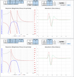
Here is a comparison of a single cycle of a 40 Hz & 100Hz sine wave being reproduced with a woofer having 4th order roll-offs at 20Hz and 200Hz. In each pic, the upper plot set is for minimum phase filters. The lower plot set uses linear phase filter for the 200Hz LP filter. You can see that the delay for the start of the up-swing is removed, but you do get a small pre-ring...more noticeable on the 100Hz example.
Attachments

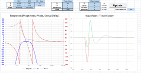
See attached pic. Your waveform for “a.” is pretty straight forward and is what the OP desired. But, I am not sure what you are describing for “b.” Is it waveform “b.1” which is a single cosine cyle? Or is it “b.2” which is the single cosine wave shifted down by its amplitude so it looks similar to a Gaussian pulse.a. Starting the one period pulse at 0 deg, where mag is zero, but phase is off 45 degrees as has been pointed out. (Iow, same as previously described) vs...
b. starting the pulse at 90 deg, where phase is zero but mag is maximum.
This sounds like the waveform was “b.2” which has much reduced HF content. But, it requires response flat to DC to properly trace it. If you don’t have response to DC, your waveform will distort as it “tries” to center itself around zero. An example is attached. On the other hand, if you were using “b.1”, that has even more HF content than “a.”. You should be able to hear clicks even in your VHF tweeter (>6300Hz) with that....the 90 degree start significantly reduced the volume of the mid driver thud compared to the 0 deg start. I'd even call it audibly insignificant.
I’m not sure what you mean by “phase not starting and stopping at zero”. Phase is a descriptor in the frequency domain. It isn’t something that starts and stops in the time domain. Phase shift in the frequency domain equates to delay in the time domain where we are observing the waveform.So my laymen's takeaway is that the abrupt start-stop of magnitude had comparatively little effect compared to phase not starting and stopping at zero. Pls correct if that's a bad takeaway...
Attachments

Yes: from the Bodzio Software' Ultimate Equalizer Manual.
20 Hz Linear Phase Sqare wave woofer output.
According to the manual:
Linear-phase loudspeakers are accurate. You feed square wave into it, and square wave comes out acoustically. You feed a one-sided transient into it, and practically identical transient comes out acoustically too. Square-wave comparative measurements of the band-limited subwoofer from Figure 27, are shown below.
See attached pic. Your waveform for “a.” is pretty straight forward and is what the OP desired. But, I am not sure what you are describing for “b.” Is it waveform “b.1” which is a single cosine cyle? Or is it “b.2” which is the single cosine wave shifted down by its amplitude so it looks similar to a Gaussian pulse.
This sounds like the waveform was “b.2” which has much reduced HF content. But, it requires response flat to DC to properly trace it. If you don’t have response to DC, your waveform will distort as it “tries” to center itself around zero. An example is attached. On the other hand, if you were using “b.1”, that has even more HF content than “a.”. You should be able to hear clicks even in your VHF tweeter (>6300Hz) with that.
I’m not sure what you mean by “phase not starting and stopping at zero”. Phase is a descriptor in the frequency domain. It isn’t something that starts and stops in the time domain. Phase shift in the frequency domain equates to delay in the time domain where we are observing the waveform.
Sorry for the lack of clarity re "b."
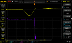
It was a single sine where the generator shifted the start phase 90 degrees, and looks like "b.2" per your chart. Scope screen shot of mixer output is attached, which looks like it shows some of the distortion you described.
So the sub, mid, HF listening comparison i posted in #80 was your straightforward a. vs your b.2.
I realize phase is a relative descriptor vs frequency....guess it would have been more proper to say the wave begins where its magnitude is flat (top of sine).
Thx for the ongoing help and instruction, including the
minimum vs linear phase plots from your other post. 🙂
Attachments
You ever try to mic a sub when you send it a square wave signal?
I guess you were meaning mic the sub alone? ...
...to bring our attention to all you get is a sine wave type look?
(without the full range odd harmonics fill ins to make it look square.)
That I've done. Sub alone sucks 😛
Mains alone can look good ime, once above the mains hpf.
(I haven't ever done a sub and mains together square wave test, just cause I'll only test subs outdoors and it's too much trouble to setup)
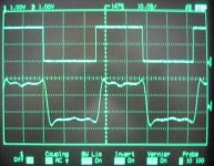
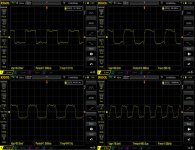
Here's a set from a MTM main (hornloaded mids and coax CD) with a 100Hz highpass.
Pretty good i think to 1kHz as shown, but once above 1k they started falling apart and weren't worth showing.
Attachments
Right. Basically the same concept as a single cycle of sine. Without the higher frequencies, the near-infinite accelerations at stop and start have no chance of being realized.I guess you were meaning mic the sub alone? ...
...to bring our attention to all you get is a sine wave type look?
(without the full range odd harmonics fill ins to make it look square.)
It's both ironic and awesome,
how we can relatively easily visualize infinite bandwidth, instant acceleration, infinite response, etc.
But then, how totally freakin difficult it is to actually physically achieve a mere 20-20kHz response with our systems !!!!!!
For me the name of the game is, ....flat mag and phase across the freq range desired, with the SPL desired, and the requisite dynamic headroom across given spectrum and SPL.. 20-20K
Sometimes I wonder how much the infinite-theory-type thinking does to retard pragmatic application development....cause how often does it even matter?
fwiw.... for any following along and not sure about square waves (which imo are actually easier than sine waves lol), .....here's a pretty good article Square Waves And DC Content: Deconstructing Complex Waveforms - ProSoundWeb.
- Home
- Loudspeakers
- Subwoofers
- Achieve good time domain behaviour to produce single cycle sine