Greetings gentlemen😱
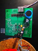
For the past month I have been working on a super regualtor project with Jung style topology, but also includes some trick from the golden reference regulator -> Buffered error amp output to the base of pass element.
The error amp is good old ne5534, voltage reference being the Jung Led reference, and for the pass elements Im using NJT4031/4030 pair...
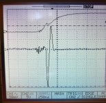
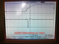
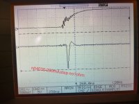
So here is basically what happened while debugging the whole assembly. The positive supply was rather successful, no magic smoke. But something rather strange happend to the negative regulator, when testing with a 200mA step, the output rings pretty badly on the oscilloscope. The ringing stops after 5-6 periods.
In the contrary, the positive reg shows a very ideal response without ringing. Voltage just goes down, negative feedback kicks in, overshoot a little, then voltage returns to the set value. Nothing more.
To tackle this ugly ringing, a few methods was tried, including: Switching pass element to slower bjt, adding input decouple cap, adding output decouple cap(aluminum, of course), increasing local feedback around erroramp. But none of these solves the problem completely, amplitude gets lower and stills rings for a while.
Anyone familiar with this issue? Thanks in advance..
---------------------------------------- Update----
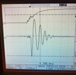
One interesting result: When using the faster driver BJT 2SA2039, the ringing was like 4 time larger in amplitude and lasts longer. When switched to MJE350 the ringing was almost stopped. Reminds me of Mr. Didden once mentioned about the error amp and pass element selection: They shall have different speed so that phase shift wont happen at the same frequency.
For the past month I have been working on a super regualtor project with Jung style topology, but also includes some trick from the golden reference regulator -> Buffered error amp output to the base of pass element.
The error amp is good old ne5534, voltage reference being the Jung Led reference, and for the pass elements Im using NJT4031/4030 pair...
So here is basically what happened while debugging the whole assembly. The positive supply was rather successful, no magic smoke. But something rather strange happend to the negative regulator, when testing with a 200mA step, the output rings pretty badly on the oscilloscope. The ringing stops after 5-6 periods.
In the contrary, the positive reg shows a very ideal response without ringing. Voltage just goes down, negative feedback kicks in, overshoot a little, then voltage returns to the set value. Nothing more.
To tackle this ugly ringing, a few methods was tried, including: Switching pass element to slower bjt, adding input decouple cap, adding output decouple cap(aluminum, of course), increasing local feedback around erroramp. But none of these solves the problem completely, amplitude gets lower and stills rings for a while.
Anyone familiar with this issue? Thanks in advance..
---------------------------------------- Update----
One interesting result: When using the faster driver BJT 2SA2039, the ringing was like 4 time larger in amplitude and lasts longer. When switched to MJE350 the ringing was almost stopped. Reminds me of Mr. Didden once mentioned about the error amp and pass element selection: They shall have different speed so that phase shift wont happen at the same frequency.
Attachments
Last edited:
A couple of things that might help. The ESR of the load caps of a Jung regulator is quite important, with higher tending to be better. May be worth putting a low value, say 0.47ohm series resistor in with any that run off the output. I suspect the NE5534 is not a fully symmetrical device internally and may have different positive and negative slew rates. It will also likely have different positive and negative PSRR. I would suggest getting your opamp decoupling caps connected directly across the opamp power pins and if you can decouple them from the power source (the output rail?) with a small value resistance (say 47 ohms) without losing important voltage headroom it would be good for stability and unwanted circuit interaction. If you are feeding the reference from the output rail try extra RC decoupling before the reference as some HF may be creeping through here.
John
John
I made a lot of Walt Jung regulators, and now a couple of years ago shunt regulator, the operational amplifiers were NE5534, AD825, AD817, AD711, the capacitors were always low esr, even OS-CON and I never had any problems.
I currently have a 4A version that I use to power the A-class amplifier and it works great.
I have to mention that the versions with NE5534 had the worst results.
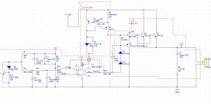
And a scheme would help.
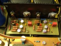
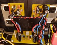
In the photos , Jung's shunt regulator +/- 5V in my DAC and +/- 19V 4A for Hiraga 'Le monstre'.
I currently have a 4A version that I use to power the A-class amplifier and it works great.
I have to mention that the versions with NE5534 had the worst results.
And a scheme would help.
In the photos , Jung's shunt regulator +/- 5V in my DAC and +/- 19V 4A for Hiraga 'Le monstre'.
Attachments
A couple of things that might help. The ESR of the load caps of a Jung regulator is quite important, with higher tending to be better. May be worth putting a low value, say 0.47ohm series resistor in with any that run off the output. I suspect the NE5534 is not a fully symmetrical device internally and may have different positive and negative slew rates. It will also likely have different positive and negative PSRR. I would suggest getting your opamp decoupling caps connected directly across the opamp power pins and if you can decouple them from the power source (the output rail?) with a small value resistance (say 47 ohms) without losing important voltage headroom it would be good for stability and unwanted circuit interaction. If you are feeding the reference from the output rail try extra RC decoupling before the reference as some HF may be creeping through here.
John
Hi John,
thanks for the tips! The electrolytes are in series with 1Ohm resistor to prevent oscillation from the beginning. Yep, I am also suspecting the NE5534 is not working nicely when it is referencing from its positive side? But no decoupling is used for the opamp supply pin, since it will add capacitance directly to Vout and cause similar issue with the electrolytes.
You are right, the Vref is worth checking. Perhaps something happened during the fast transient..😎
I have to mention that the versions with NE5534 had the worst results.
And a scheme would help.
In the photos , Jung's shunt regulator +/- 5V in my DAC and +/- 19V 4A for Hiraga 'Le monstre'.
Yes, I am aware that NE5534 is only mediocre compared to those faster amps, but it has better phase margin and much lower price😀 After debugging I`ll just solder more expensive ones on the board. But as John mentioned above, the NE5534 could be the cause as well, will look into it..
I suppose you didn't put all those diodes D2,D3,D18 and D19 in ?
With an output of only 6V one diode is ok, two is to much.
Mona
With an output of only 6V one diode is ok, two is to much.
Mona
Sorry, the voltage divider was changed to 2K:383Ohm to get an output of approx. 15V. The zener is just one with 7.5V.
I get what you say about having no decoupling on the supply pins so as not to put additional capacitance on the output supply rails but I do think any opamp will work better with some. The opamp supply current is a fairly constant 5-10mA so a 10uF Tantalum, possibly bypassed with a 100nF COG ceramic across the opamp supply terminals fed from VEE/VCC by a 47 - 100 ohm resistor will separate the feeds and decouple with no ill effect on the output response IMHO.
The amount of ESR required in the load capacitors reduces with a greater load current and greater value of capacitance used. The effective regulator output inductance reduces with load current and the series resistance required to give critical damping to the series resonant circuit formed at the regulator output will depend on both this ESL and the load capacitance. Looks like Grunf has used high value load capacitance and is supplying high currents which might explain his lack of concern about ESR?
I've noticed a couple of other things which you could try to eliminate causes, perhaps before trying the opamp decoupling. You could try temporarily removing C21 and C22 as these serve to reduce the gain and phase margin of the feedback circuit. You could also temporarily feed the opamp supply from the input rail, and separately try feeding the voltage reference (R26) from the input rail. Each of these are potential paths for unwanted stray feedback. The filtering you have on the voltage reference looks OK but the low frequency impedance as seen by the opamp input terminals is not the same for both. It should ideally be around 500 ohms to minimise LF noise and be the same on both to negate the effects of input bias current to the opamp. I'm not sure if this last point could have any bearing on the step response of the overall circuit.
Finally, have you considered a different opamp that doesn't require extra frequency compensation for low gains such as the AD825?
John
Last edited:
Started with the simplest method: Shorting resistor to the electrolyte on output and it turns out to be the right one!
With the panasonic FM series directly paralelled to output, the dynamic response is much improved. No ringing this time at least, though output Z seems to be increased -> With 200mA step, the output drops at least 1V, no matter what pass element was used😕 In the positive supply, delta V is always within 350mV. Perhaps dual positive supply with separate transformer winding is the simplest solution to better performance and BOM...
I think this might be indicating a over-damped system behaviour, so next step will be increasing the resistor very slowly to find a sweet point. Hopefully some guru here can somehow explain the mathematics behind this😀
Attachments

I've noticed a couple of other things which you could try to eliminate causes, perhaps before trying the opamp decoupling. You could try temporarily removing C21 and C22 as these serve to reduce the gain and phase margin of the feedback circuit. You could also temporarily feed the opamp supply from the input rail, and separately try feeding the voltage reference (R26) from the input rail. Each of these are potential paths for unwanted stray feedback. The filtering you have on the voltage reference looks OK but the low frequency impedance as seen by the opamp input terminals is not the same for both. It should ideally be around 500 ohms to minimise LF noise and be the same on both to negate the effects of input bias current to the opamp. I'm not sure if this last point could have any bearing on the step response of the overall circuit.
Finally, have you considered a different opamp that doesn't require extra frequency compensation for low gains such as the AD825?
John
Hi John,
really appreciate your suggestions! I was fortunate enough to avoid a Nichicon ultra low Z electrolyte sitting around in my closet, that stuff would definitely cause other issues.
Yes, C21 and C22 reduces the gain of error amp quickly to unity to avoid oscillation in the original design. However, IMHO if the layout is optimized with regard to parasitics, especially the parasitics or time delay to the error amp, one can actually reduce C21 and C22 in order to "deplete" this advantage. Increased bandwidth and lower Z at high freqs, for example. Of course, stability has the highest priority.
Unbalanced input resistance could indeed cause problems with DC offset, but this application is quite tolerant with output accuracy. In the end, the LED reference has already some deviations..
I am considering at this point seriously supplying the Error amp and Vref directly from input voltage. No strange feedbacks to worry about. Simply Vin- as close to Vout as possible...
The internal compensation of the NE5534 is referenced to the positive op amp supply so bypass across the amp supply pins shouldn't be needed in this application
assuming you are using a model that does the comp pins correctly then why don't you have a Ccomp as recommended for unity gain?
assuming you are using a model that does the comp pins correctly then why don't you have a Ccomp as recommended for unity gain?
Hi,
error amp in the Jung Regulator should be working at very gain, at least in lower frequencies in order to achieve very low output Z. The article from Jacknini also shows the crazy output Z as low as a few micro Ohm.
But I have also seen regulators with a local feedback loop closed around opamp, perhaps it increases effective bandwidth of the regulator. I personally havent tried such methods.🙂
Typo, "working at very high gain".
Update--------
My fault, it is indeed a non inverting amp with low gain in Jung SR..... But the Ccomp is only relevant with THD isnt it? And Ccomp reduces Slew Rate, could be bad for the transient response.
Update--------
My fault, it is indeed a non inverting amp with low gain in Jung SR..... But the Ccomp is only relevant with THD isnt it? And Ccomp reduces Slew Rate, could be bad for the transient response.
Last edited:
The Ccomp is to keep the op-amp stable at closed loop gains of less than 3. Your circuit needs it as it is operating at a gain of 1.5 and reducing to unity gain beyond 1.6kHz. Add the additional phase shift of the output cap and the two series transistors and you are dicing with instability.
Just noticed that when you are supplying the opamp from the regulated output it is only getting circa 3.75 volts. That deffo won't be enough for best performance and you will need to make sure the output operates at mid supply rail voltage. I'd suggest replacing D2 and D3 with something like a single green LED.
John
- Home
- Amplifiers
- Power Supplies
- Intrinsic instability in a negative Jung style regulator?