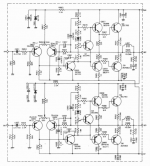
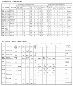
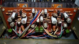
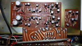
Hello, looking for some help restoring a surprisingly well built, decent sounding Nikko TRM-600 integrated amp circa 1976. Visual inspection showed all parts fine, filter caps look too good for 45 years w/ not a hint of hum. I left it on a 40W DBL for half a day to start but no sound on full power, tried a phone jacked into the pre-out/amp-in and it played music ok, so I Deoxited and worked all the bells and whistles and RCAs (and there are a lot) and got it playing. Did the bias and offset (Deoxited trimmers held up!) and got it in spec and it’s rock solid, playing well with its original mates, beat up Dynaco A25s that I also patched up. Amp sounds better than it should but it’s really too warm, bass heavy, and wooly, it’s been a long time since high school and I recall bassy and and warm was the goal back in ’76, but I think a complete recap should tighten and brighten it up for the better. I’m a sophomore e-tinkerer, been reading the forums/blogs but have a few questions. Below are the amp and preamp schematics, sorry it’s the best image resolution I could get from the PDF manual. Picts are from web, thanks go out to orig poster.
- I’m looking for advice regarding value or harm of using bipolar ES Muse caps for the 10uF caps doing coupling duty throughout the amp. If people here nix the idea it’ll be usual polar FC/FM/FR or KZ/FW instead. The .47 and 1uF couplers will get film caps. Is bipolar ES Muse a waste of effort?
- Can someone point out the feedback circuit in the amp? I think it’s R667/C657. The only pf caps here are both discs, C657 and C661, leave well enough alone or try and sub polystyrenes? Tight, risky soldering here. Always worried of a trace lifting, it would be a hard fix.
- I’ve included the list of transistors and diodes in the amp, if anyone spots ones known to be unreliable/noisy let me know as I’ll add their substitutes to my parts order and swap them out while I’m in there or at least set them aside for the future. The one that concerns me is the 2SA539 at inputs, but the amp is otherwise quite. And yes, I know, don’t shotgun it, do one thing, one stage, one channel, at a time.
- I plan to up the filter caps from 6.8KuF to 10KuF unless people think the old S2HB10 8A/100v bridge will fail, it’s a TO-3 case so that would not be good. Go for it?
- This amp has speaker breakers not a relay protection circuit. I sprayed them out too and worked the buttons a bunch, no idea if they are working properly, obviously they close and pass audio but will they open on a short? Plus are these terrible sound-wise? Plenty of modern high quality hifi doesn’t use any speaker protection, is it stupid to bypass them? Anyone know if I can get new production drop in replacements? Mouser/Digikey link? I saw Velleman makes a relay protection board I could fit somewhere but I’d like to leave it looking as un-kluged as possible.
- It has a breaker for the mains too, I will leave it but maybe I should stick a real fuse in line with it? I'm in the EU/240V, amp's probably 30W, 2A slow-blow about right?
Any guidance will be much appreciated.
Attachments
Last edited:
The feedback is indeed ------- R667/C657 ||| R668/C658.
C661/C662 are COMPENSATION capacitors --do NOT change them they stablise the total circuit -IE- chosen for that particular circuit design by the actual audio designer.
IF you are going to change BJT,s to "uprate them " and change values of resistors and capacitors you are in effect changing the design specifications THEN you might have instability problems which might cause you to then change the values of those 50pf capacitors .
Best result is it improves the stability but that's a big if as a rise in amplification in the signal path might mean improvement in some areas it can also cause instability.
- I’m looking for advice regarding value or harm of using bipolar ES Muse caps for the 10uF caps doing coupling duty throughout the amp. If people here nix the idea it’ll be usual polar FC/FM/FR or KZ/FW instead. The .47 and 1uF couplers will get film caps. Is bipolar ES Muse a waste of effort?
I've been extensively using Wima MKS2s for most solid state coupling duty when doing restorations like you are, the reason being they are so miniaturized they are usually pretty close to the size of the equivalent electrolytic, and that pretty much any decent film cap is far better than the best electrolytic. I've had excellent results using these. They are, in my experience, the only film caps I can usually be certain they will fit where a coupling electrolytic was.
The reason they are smaller than most film caps is they're not the very premium film types (such as polypropylene or teflon - these tend to be much larger) but metallized polyester (PET).
BTW - they go as high as 10uF in these miniaturized types.
The preamp section sucks. I restored the One that I have, leaving the Power amp with new capacitore, 10 kF supply caps and new diodes. No circuit breakers. It's ok for 8 Ohm loads, with 4 ohm there's High risk to destroy it


