Hi.
I am refurbishing 2 Marantz 240 for a friend.
My friend says that they work but make bad sound.
Earlier interventions by other people ( pros they said !) have made a mess almost everywhere.
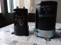
Replaced original big caps with "plastic ones" (on the phot, the new good ones are on the right, they weight 560g instead of 250g for the plastic ones ....), put very small low quality electrolytics, did very bad solders, forget to clean the boards and remove solder between tracks, ...
But that was before I look at the power trans.
Let's have a look !
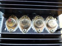
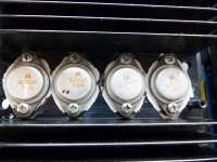
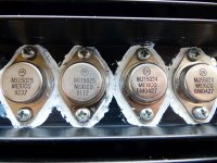
Only one quadruplet is original (I think they were voltage-and-hFE-selected 3055 or 3773), and the others are a mix between real and "weird looking" models (no, I didn't say fakes, I just think about it !!!), between MJ15015/16, MJ14024/25 of various kinds and batches ...
I have not tested them but I doubt they are appaired...
I'll test them today but what should I do :
- keep the originals ones and change the others ?
- change all of them ?
- replace with 15015-16, 15024-25 or 21193-94 ?
I thank you for your kind replies and advices !
I am refurbishing 2 Marantz 240 for a friend.
My friend says that they work but make bad sound.
Earlier interventions by other people ( pros they said !) have made a mess almost everywhere.
Replaced original big caps with "plastic ones" (on the phot, the new good ones are on the right, they weight 560g instead of 250g for the plastic ones ....), put very small low quality electrolytics, did very bad solders, forget to clean the boards and remove solder between tracks, ...
But that was before I look at the power trans.
Let's have a look !
Only one quadruplet is original (I think they were voltage-and-hFE-selected 3055 or 3773), and the others are a mix between real and "weird looking" models (no, I didn't say fakes, I just think about it !!!), between MJ15015/16, MJ14024/25 of various kinds and batches ...
I have not tested them but I doubt they are appaired...
I'll test them today but what should I do :
- keep the originals ones and change the others ?
- change all of them ?
- replace with 15015-16, 15024-25 or 21193-94 ?
I thank you for your kind replies and advices !
Attachments
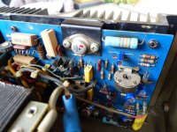
Whats your problem with the caps? The LNT are looking fine to me 😕. On the board there were the axial type capacitors replaced by some radial type. Well, not ideal. But not a big problem either if capacitance and voltage rating is fine. Technology has grown - size has shrinked.
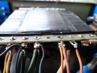
That first photo is a glaring example of how not to solder and an excess of thermal conduction material can actually increase the temperature of the active devices .
If you were building your own PC would you splash on large amounts to the CPU ? if you check up only a small amount is required.
It looks rushed .
The original BJT,s on the left are old school ( FIRST picture ) , the ones on the right are more modern .
MJ15024/5 have the same specifications but I am not keen on buying different company versions of them I like to keep them the same .
I don't have a problem with the different size of the large capacitor as long as its the same or better quality.
After checking I was right to be concerned with the different BJT,s at the output here is a blog by a guy who actually worked in Marantz at the time they were made .
For those of an opposite opinion PLEASE ! read his comments on the great lengths the company went to to match them.
HiFi Collector: Power Amplifier - Marantz 240
For those of an opposite opinion PLEASE ! read his comments on the great lengths the company went to to match them.
HiFi Collector: Power Amplifier - Marantz 240
How Much Thermal Paste is Too Much: Get the Exact Answer
While this is how to apply thermal paste to a CPU exactly the same technical principles apply to output active devices in power amplifiers.
While this is how to apply thermal paste to a CPU exactly the same technical principles apply to output active devices in power amplifiers.
Sorry, but I tried 3 times to post an answer and each time got a message telling a security token was missing ...
A "security token " is usually web-server talk for a cookie of some sort so that the website recognizes you .
I turned off two of my tracking blockers as they would have interfered with access to DIY Audio.
If its any consolation my own ISP stopped me accessing their website as they got different security features coded in in their web-server.
Those features included forcing people to use Google which being a freedom loving person I refused to do, as a result I pay £3/quarter for snail-mail delivery of calls used etc.
For my initial post, I hadn't filled my profile
But after, I filled my profile and added my country (France) .
Could it be the same problem as HiFiEngine who, since 3-4 months, refuses french adresses ?
But after, I filled my profile and added my country (France) .
Could it be the same problem as HiFiEngine who, since 3-4 months, refuses french adresses ?
I did some tests on the power transistors of the 2 Marantz 240 I am refurbishing.
The results corresponds with the four trans of each of the 4 boards. I named this « quadruplets » , without regards to the type(NPN or PNP) of each trans. First number is for the leftmost trans, 4th number for the rightmost one.
Quadruplet 1 (the board with the sideways marked MJ15015)
132 – 169 – 297 – 17
The first two numbers seem quite well balanced.
But the other two are strange. 297 is way too much an hFE. 17 is on the lean side. The two are quite a mismatch !
I did the tests 5 times, cleaning the pins ans the probes, and using a new battery on the tester, with the same results.
On the datasheets, Moto (or On Semi) says hFe between 10 and 70 for these parts.
Quadruplet 2 (the board with the « good markings » MJ15015 and MJ15016)
48 – 12 – 222 – 222
Here again, 12 is rather low. And the two with222 are magic !!
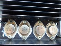
Quadruplet 3 (the board with the original SJ2519 and SJ2520)
112 – 61 – 89 – 47
These are the only original trans, and are quite a mismatch. For each pair, one trans have almost twice the hFE of the other.
Quadruplet 4 (the board with the MJ15024 and MJ15025)
129 – 94 – 43 – 42
The 4 trans on this quadruplet are the most appaired. But the pairs are not equal.
These tests have been made with the trans still on the heatsinks.
And while writing this, I see on the manual that the trans have only the emitters separated, the collectors and bases are joined.
Wrong tests …
I think I’ll have to disassemble all the trans and tests them alone …
The results corresponds with the four trans of each of the 4 boards. I named this « quadruplets » , without regards to the type(NPN or PNP) of each trans. First number is for the leftmost trans, 4th number for the rightmost one.
Quadruplet 1 (the board with the sideways marked MJ15015)
132 – 169 – 297 – 17
The first two numbers seem quite well balanced.
But the other two are strange. 297 is way too much an hFE. 17 is on the lean side. The two are quite a mismatch !
I did the tests 5 times, cleaning the pins ans the probes, and using a new battery on the tester, with the same results.
On the datasheets, Moto (or On Semi) says hFe between 10 and 70 for these parts.
Quadruplet 2 (the board with the « good markings » MJ15015 and MJ15016)
48 – 12 – 222 – 222
Here again, 12 is rather low. And the two with222 are magic !!
Quadruplet 3 (the board with the original SJ2519 and SJ2520)
112 – 61 – 89 – 47
These are the only original trans, and are quite a mismatch. For each pair, one trans have almost twice the hFE of the other.
Quadruplet 4 (the board with the MJ15024 and MJ15025)
129 – 94 – 43 – 42
The 4 trans on this quadruplet are the most appaired. But the pairs are not equal.
These tests have been made with the trans still on the heatsinks.
And while writing this, I see on the manual that the trans have only the emitters separated, the collectors and bases are joined.
Wrong tests …
I think I’ll have to disassemble all the trans and tests them alone …
For my initial post, I hadn't filled my profile
But after, I filled my profile and added my country (France) .
Could it be the same problem as HiFiEngine who, since 3-4 months, refuses french adresses ?
Hi-Fi Engine blocks me as well now (it didn't at first ) as it thinks I am a bot.
As I said an employee of Marantz stated the output devices MUST be within a small margin of HFE to obtain the specifications of the amplifier so they must be matched.
Last edited:
If you are concerned about the Hfe match between output devices, use the MJ2113/4 (or 5/6) ONLY. Unless you want to buy an ungodly number of 15024/5 devices to select from. The Hfe match on that process is inherently better. Normally, I wouldn’t mess with Hfe match other than using the same batch, because my circuits don’t require it. Some do benefit - especially at a point in time where gain was hard to come by. It depends on the gain structure with the global NFB loop - how much local FB and where it is applied. And whether you are willing to chase a 4th decimal place in distortion figures.
I would be concerned about using 15015/6 from both a matching and ruggedness standpoint. Matching on that process is just awful - especially the NPN to PNP., but even between devices in the same rail. They were supposed to be CHEAP, and at one time they were. And they are not strong enough to use, IMO, on any amplifier that used 80 volt rail caps. Especially with only two in parallel. The supply voltage has got to be above +/-60V or they would have used 63V caps. Amplifiers that successfully used those transistors in those days used as many as SIX in parallel (QSC Model 41, for example).
I would be concerned about using 15015/6 from both a matching and ruggedness standpoint. Matching on that process is just awful - especially the NPN to PNP., but even between devices in the same rail. They were supposed to be CHEAP, and at one time they were. And they are not strong enough to use, IMO, on any amplifier that used 80 volt rail caps. Especially with only two in parallel. The supply voltage has got to be above +/-60V or they would have used 63V caps. Amplifiers that successfully used those transistors in those days used as many as SIX in parallel (QSC Model 41, for example).
A couple suggestions based on having restored seversl of these.
There are several versions. Be sure to use correct service manual. I can help if you're having a problem getting the correct one.
More often than not these have been worked on previously, and not always very well. I walk through the circuit and compare to correct schematic. Replace components that don't match originals.
It is important to follow the recommendations in the service manual with regards to Hfe rank for the outputs. I can give you modern part numbers for most of the transistors. The drivers are tricky. No TO66 replacement but can make a TO220 work. Can also find these on Ebay for abou $30.
Feel free to drop me a PM with any questions. That will make it easier to send documents.
Hi.
I am refurbishing 2 Marantz 240 for a friend.
My friend says that they work but make bad sound.
Earlier interventions by other people ( pros they said !) have made a mess almost everywhere.
Replaced original big caps with "plastic ones" (on the phot, the new good ones are on the right, they weight 560g instead of 250g for the plastic ones ....), put very small low quality electrolytics, did very bad solders, forget to clean the boards and remove solder between tracks, ...
But that was before I look at the power trans.
Let's have a look !
Only one quadruplet is original (I think they were voltage-and-hFE-selected 3055 or 3773), and the others are a mix between real and "weird looking" models (no, I didn't say fakes, I just think about it !!!), between MJ15015/16, MJ14024/25 of various kinds and batches ...
I have not tested them but I doubt they are appaired...
I'll test them today but what should I do :
- keep the originals ones and change the others ?
- change all of them ?
- replace with 15015-16, 15024-25 or 21193-94 ?
I thank you for your kind replies and advices !
I am just guess they may have been repaired previously. If its stock, the thermal paste would have totally dried up by now.
After all this times, the beasts are roaring again !
What I did :
- change all the power trans with 29193-194
- tested all the other trans.
- found one MPSA64 HS, replaced with new one
- put new thermal grease all over
- added 150pF ceramic caps on the RCA inputs
- added 0,1µF 250V film caps on the secondary outputs of the transformers
- changed lamps for blue LEDs
- added 1N4004 as service bulletin said
- tested and measured :
on the 4 channel amps, offset is between 0.9 and 1.3 mV, bias is between 12.9 and 13.3 mV.
They sound beautiful !
Thanks all for the help !
- Home
- Amplifiers
- Solid State
- Marantz 240 transistor mess