Hello,
on an amp with a KBPC3510 diode bridge and a 16V 15mF capacitor to get 10 V, 3.5A (worked for years without a problem) I could see ringing, tried all kinds of snubbers, C across diode, R+C and C||R+C but nothing worked.
Tried BYV29-500 (ultrafast rectifier diodes, If(av)=9A, trr<60ns) and the capacitor was cooked in 30 seconds, diodes are still o.k.
Please explain why and how to avoid it, Thank You.
Edit: all diodes are installed the correct way.
Edit 2: installed a new capacitor and it works now, I guess just bad luck...
Attachments
Last edited:
It's unlikely because of ultrafast diode type. It is most likely you put one of diodes in a wrong direction. So AC voltage and current killed the cap very fast.
Ringing - it could be some (oscilloscope?) common mode noise.
Ringing - it could be some (oscilloscope?) common mode noise.
Last edited:
The diodes are the only thing that changed and I checked the diode orientation before and afterwards and they are all installed the correct way.It's unlikely because of ultrafast diode type. It is most likely you put one of diodes in a wrong direction. So AC voltage and current killed the cap very fast.
The ringing is from the switching noise of the diodes.Ringing - it could be some (oscilloscope?) common mode noise.
How do you know the capacitor is cooked? What does 'cooked' mean?
How did you measure the ringing?
Jan
How did you measure the ringing?
Jan
Last edited:
The top (valve) opened and it was burning hot.How do you know the capacitor is cooked? What does 'cooked' mean?
Just looking at it on an oscilloscope, every 10ms the typical ringing.How did you measure the ringing?
Do you have any suggestions for me ? Neither the Morgan Jones values (Linear Audio | your tech audio resource), nor the Mark Johnson values (Linear Audio | your tech audio resource) worked for me and the old way of putting 10nF parallel to the diodes didn't work either....
The measurement points are very critical, to be sure you are measuring the right thing. That's why I asked.
As to the cap, just replace it with something you have at hand so at least you can verify that the rectifier stuff is OK.
If that one gets cooked too, that's a clear diagnostic ;-)
Jan
As to the cap, just replace it with something you have at hand so at least you can verify that the rectifier stuff is OK.
If that one gets cooked too, that's a clear diagnostic ;-)
Jan
I see something between sawtooth and sinus and the ringing. I used a potentiometer and the suggested C-values, but I couldn't see any change in the ringing...still hopening for some epiphany moment.The measurement points are very critical, to be sure you are measuring the right thing. That's why I asked.
I did that already 🙂As to the cap, just replace it with something you have at hand so at least you can verify that the rectifier stuff is OK.
If that one gets cooked too, that's a clear diagnostic ;-)
Edit 2: installed a new capacitor and it works now, I guess just bad luck...
Well at least that works then.
What I meant by the critical measurement is the following. The scope 'measures' what is between the point where you attach the ground clip and the probe tip. Supply noise and switching junk can and is different at different points along the supply system, especially along the grounding paths.
So you will measure different things depending on where you clip the ground clip of the scope. One way to start is to measure directly on the rectifier capacitor. What do you see there?
Jan
15mF means 15000uF, so obviously an electrolytic.wrenchone Top valve opening? What kind of capacitor are you using? It should be a film or ceramic type,.
The 16V capacitor and 10V 3.5A supply rating should have been a hint 🙂
We are so used to people writing units wrong, than when used properly we get confused 😀
As of the "mystery problem" I strongly suspect miswiring of any kind.
And that "ringing", if real, is not a problem at all, just caused by "listening with your eyes" 🙂
Lots of people get a scope, scope everything and sometimes get worried by what they "see".
On stuff which works fine.
I compare that to using STRONG magnification; suddenly your beloved´s perfect skin becomes a Moon landscape, full of crater type pores 🙄
Nothing wrong of course, just a different point of view and magnification.
Yeah, I see now that he's complaining about smoking his bulk filter cap, not the snubber cap. The only thing that could do that quickly is reverse polarity or gross overvoltage -I would suspect the former.
Potentiometer with long wires won't help much. If you want a good RC-snubber - it have to be as short as possible. Constant resistor (from several to ten Ohms, 0.5-1W rated) and film cap, for example 0.47-1.0 uF (up to 2-3 uF), across secondary before a bridge. No longer than 6-9 centimetres both.I see something between sawtooth and sinus and the ringing. I used a potentiometer and the suggested C-values, but I couldn't see any change in the ringing...
Last edited:
JMFahey, that sounds a bit like that guy who said, we should test less so we have less cases 
But I get your point.
Jan
But I get your point.
Jan
O.k. the whole thing started because of the noise on the secondary of the OPT of this 845 SE amp. The PowerTransformer and the OPT have the same orientation and between the two is a choke 90°. In order to get the noise down I added a common mode choke and two 4m7 capacitors to the heater wiring of the 845, this helped visible and audible 😀.Well at least that works then.
What I meant by the critical measurement is the following. The scope 'measures' what is between the point where you attach the ground clip and the probe tip. Supply noise and switching junk can and is different at different points along the supply system, especially along the grounding paths.
So you will measure different things depending on where you clip the ground clip of the scope. One way to start is to measure directly on the rectifier capacitor. What do you see there?
Jan
The setup is like this: secondary - diode bridge - (bad) 15 mf capacitor - common mode choke - (good) capacitor 2x 4m7 - 845 heater (fixed bias).
Changing the diode bridge from KBPC3510 to BYV29-500 'cooked' the 15mF cap, but the two 4m7 didn't get warm. After exchanging the 15mF while still using the BYV29-500 everything worked. Changed back to the KBPC3510 because there is no room for heatsinks for the BYV29-500.
I still don't understand why the cap was blown, but I am more interested in lowering the noise.
I probed at the OPT and at the diode bridge with similar results.
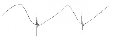
The scope shows what I think is diode ringing at the diode bridge and at the OPT. I see a trace that looks like a crossover between a sawtooth and a sinus and what I think is called ringing in the 'valley'. Sorry no digital scope, please look at the rough draft.
Attachments
Depending on how you connected the scope, the picture seems to show ringing when the diodes start to conduct instead of turn off. But you may also have the phase upside down.
As I said, it often depends on exactly where you connect the scope ground. So you must be specific. 'Measured at the diode bridge' doesn't really explain what exactly you measured.
Can you measure directly on the 1st cap after the rectifier? Scope ground clip as close as possible to the cap neg terminal, probe as close as possible to the cap pos terminal.
Also, is there other equipment or the amp itself connected to ground? Try to scope the top of the capacitor with the scope ground clip unconnected. You probably will see much more noise and 50 or 60Hz, but check if you still see the ringing.
Jan
15mF means 15000uF, so obviously an electrolytic.
The 16V capacitor and 10V 3.5A supply rating should have been a hint 🙂
We are so used to people writing units wrong, than when used properly we get confused 😀
No one except US and US orientated countries uses milliFarad, that is why. The world standard is µF. Same with 10,000 µF or 10.000 µF. Or µµF which the world calls picoFarad or pF. Or mho for conduction (Ohm in reverse 😉) which the world calls Siemens.
Last edited:
I tried :Potentiometer with long wires won't help much. If you want a good RC-snubber - it have to be as short as possible. Constant resistor (from several to ten Ohms, 0.5-1W rated) and film cap, for example 0.47-1.0 uF (up to 2-3 uF), across secondary before a bridge. No longer than 6-9 centimetres both.
10nF across the diodes
Cs=1nF Rs=1k
Cx=10n Cs=200n Rs=2k potentiometer, max. 6cm wires
Cx=200n Cs=100n Rs=2k potentiometer, max. 6cm wires
Cs=470nF Rs=5
Cs=470nF Rs=10
Cs=940nF Rs=5
Cs=940nF Rs=10
...absolutely no change...
Absolutely no change means you are trying to fix something else than what you are measuring. As I tried to explain.
Jan
Jan
I am sorry, I should have been more specific, I just sketched what I measured most of the time - this is from the OPT, no problem to hook up the ground clip.Depending on how you connected the scope, the picture seems to show ringing when the diodes start to conduct instead of turn off. But you may also have the phase upside down.
The attached photos are done with 2x 4m7 instead of the blown 15mF at the diode bridge and look completly different.
I don't think I can put the ground clip on the negative cap terminal, this is a DHT heater circuit. Therefore I attached the ground clip to the 0 V reference. The AC photo is done with the probe at the AC of the bridge rectifier, the DC photo has the probe at the + terminal of the bridge and the differential has one probe at the neg terminal and one probe at the positive terminal . Thank you for helping, please tell me if you need more !As I said, it often depends on exactly where you connect the scope ground. So you must be specific. 'Measured at the diode bridge' doesn't really explain what exactly you measured.
Can you measure directly on the 1st cap after the rectifier? Scope ground clip as close as possible to the cap neg terminal, probe as close as possible to the cap pos terminal.
Also, is there other equipment or the amp itself connected to ground? Try to scope the top of the capacitor with the scope ground clip unconnected. You probably will see much more noise and 50 or 60Hz, but check if you still see the ringing.
Jan
Attachments
- Home
- Amplifiers
- Power Supplies
- Why gets the capacitor cooked ?