I have a jfet question. I have a jfet with a 25v gate to drain voltage rating that I would like to run at a higher voltage. If I measure the exact gate to drain breakdown voltage limiting the current so not to exceed it's power rating does that harm the device ?
Here is a very generic rule in electronics...
A Voltage higher than rating => Damage
A Voltage much higher than rating => Destruction
Pretty simple.
A Voltage higher than rating => Damage
A Voltage much higher than rating => Destruction
Pretty simple.
You have to derate those TO-92 packages for power, due to their high thermal resistance.
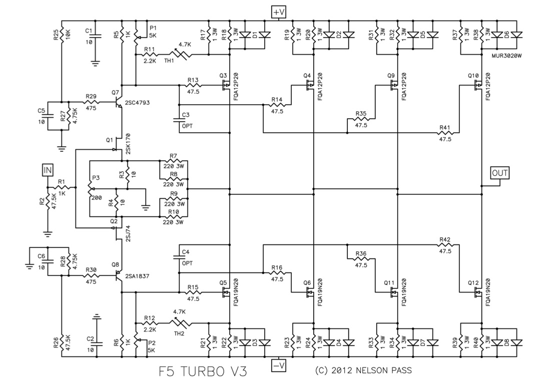
Use a cascode transistor to take the extra voltage, like this example.
https://www.diyaudio.com/forums/gallery/data/500/F5Tv3_schematic.jpg
Use a cascode transistor to take the extra voltage, like this example.
https://www.diyaudio.com/forums/gallery/data/500/F5Tv3_schematic.jpg
Last edited:
Woody is seeking to measure the gate-to-drain breakdown voltage of a device in his possession, and to do so in a way that is nondestructive and non-harmful. He proposes to include active current limiting into his measurement setup, so that when the voltage becomes large enough that the gate-drain diode actually DOES break down, the measuring apparatus's current is very very small. He wonders whether this is a sensible setup.
That should be possible without damage, if done very carefully not to allow much current
as the breakdown starts. It would be a very small amount of current to control/limit.
as the breakdown starts. It would be a very small amount of current to control/limit.
Last edited:
I never attempted such a measurement, but I see no fundamental reason against it: breakdown voltage measurements on semiconductor junctions have been carried out for ages and without problem provided certain rules are observed.
There are exceptions, of course: some laser diodes, microwave diodes, etc, but in the case of a jFET, it is normally a matter of regular avalanche in a small, sensitive junction, but if the measurement is made at the µA level, for just the time needed, I don't think it will cause irreversible damage.
Just be sure to eliminate any possibilty of capacitive loading in the measurement setup, in case there is a negative resistance effect.
I may do the test, with a before/after comparison of some key parameter (to be defined) to assess the effect of an avalanche
A simple trick to extend the voltage rating of a JFET: Get a BSS159 (Infineon), CMPF4392 (On Semi), or a Supertex DN2540 or DN2530 or (Digikey or Mouser) and wire it like so: Its gate to your JFET's source, its source to your JFET's drain. This is a cascode configuration, which will operate your JFET at a few volts, but allow operation to 40V or more.
The three terminals of the combination would be
Gate=the gate of your JFET
Source=the source of your JFET
Drain= the drain of the BSS159, CMPF4392, DN2540, or DN2530
It would probably work with other high voltage depletion mode MOSFETS or JFETS as the cascode top (perhaps a power package if you're going to handle current), though I've only used these.
Last edited:
The "limit" on a JFET is often the point that gain current becomes not-very-small, not a channel breakdown. Normally we use a JFET beCAUSE the gate current is super-tiny. But if you have a plan where >pA gate current is tolerable, you may be able to raise the voltage. Gate leakage is related to hiss, so if you want real low hiss then over-voltaing is probably unwise.
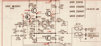
I used to select "low volt" parts for higher voltages. Works fine.
I used to select "low volt" parts for higher voltages. Works fine.
Agree.That should be possible without damage, if done very carefully not to allow much current
as the breakdown starts. It would be a very small amount of current to control/limit.
A 100V supply through a 100k resistor so maximum current = 1 mA (and that in short conditions) should not destroy a TO92 device junction.
Bipolar or FET.
When testing them I just use that (always a minimalist) and never had a problem.
I've used 60V on a 40V Jfet but only as a cascode (or common gate) and at mA currents. This does not seem cause breakdown. But the Jfet becomes very nonlinear as the field shape becomes distorted and pulled toward the drain. -Vgs vs Id will increase but in a nonlinear fashion.
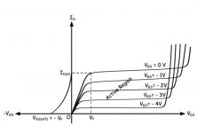
This app-note shows curve tracing beyond the Vds limit:
Biasing of Junction Field Effect Transistor or Biasing of JFET | Electrical4U
This confirms my assumption that unlike MOSFETs, A JFET gate can tolerate a limited reverse current.
Biasing of Junction Field Effect Transistor or Biasing of JFET | Electrical4U
This confirms my assumption that unlike MOSFETs, A JFET gate can tolerate a limited reverse current.
Attachments
That ohmic region is most interesting, as the curves there are the reciprocals of the transfer line but 'biased' by the Vp-Vds rate. Not always clearly visible in the graphs, though it explains a lot about the behaviour of cascodes. And being ohmic, it resembles the triode output char's topsy turvy.
- Home
- Amplifiers
- Solid State
- Jfet maxium voltage rating