In another thread, I started investigating feedback from output tube plate to driver cathode in an SE amp. It seems to work extremely well. I'm getting 0.14% distortion at 1W, harmonics above 3rd are more than 100dB down, buried in the noise. Zout is 0.8 Ohm. I've only been able to find 1 SE amp online with better distortion at 1W (Pete Millett PL-177).
I'm happy with how this is going, but I'm not going to be satisfied until I fully investigate whether there are any easy ways to make it significantly better. My plan is to substitute a high-mu transmitting triode as the output tube for this amp in the final design, so I'm going to lose some gain and feedback when I do that.
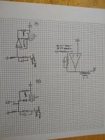
The overall approach is series-applied voltage feedback and I like to think of it like a big op-amp in series-feedback configuration with a large voltage offset at output (output tube plate) and a lower input impedance on the inverting input (see graphic). There are also undesirable AC currents that flow out of the inverting input, which is the driver tube cathode.
The question I've been asking myself lately is if there is a simple way to eliminate these undesirable AC currents that flow into the feedback network. It would also be nice if the inverting input were high-z.
I think I've come up with a couple of simple ways to accomplish this. Of course, I'm always soliciting other ideas.
A) is probably what I'll try first. It is simple to implement and the feedback of the op-amp will just make sure that the voltage at the cathode of the driver will follow the voltage at the feedback network node, no matter what the instantaneous current flow through the tube is.
B) will appeal more to those that are averse to op-amps. Diode provides a fixed bias and the p-channel fet buffers the feedback network. This one would require fine tuning the bias by adjusting screen voltage, I think. I think it will work almost as well as A)
I'm trying to avoid extra time constants as much as possible in both of these solutions.
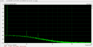
Simplified schematic of the test amp and baseline distortion result are attached.
I expect the results of testing A) to tell me whether B) is even worth pursuing.
I'm happy with how this is going, but I'm not going to be satisfied until I fully investigate whether there are any easy ways to make it significantly better. My plan is to substitute a high-mu transmitting triode as the output tube for this amp in the final design, so I'm going to lose some gain and feedback when I do that.
The overall approach is series-applied voltage feedback and I like to think of it like a big op-amp in series-feedback configuration with a large voltage offset at output (output tube plate) and a lower input impedance on the inverting input (see graphic). There are also undesirable AC currents that flow out of the inverting input, which is the driver tube cathode.
The question I've been asking myself lately is if there is a simple way to eliminate these undesirable AC currents that flow into the feedback network. It would also be nice if the inverting input were high-z.
I think I've come up with a couple of simple ways to accomplish this. Of course, I'm always soliciting other ideas.
A) is probably what I'll try first. It is simple to implement and the feedback of the op-amp will just make sure that the voltage at the cathode of the driver will follow the voltage at the feedback network node, no matter what the instantaneous current flow through the tube is.
B) will appeal more to those that are averse to op-amps. Diode provides a fixed bias and the p-channel fet buffers the feedback network. This one would require fine tuning the bias by adjusting screen voltage, I think. I think it will work almost as well as A)
I'm trying to avoid extra time constants as much as possible in both of these solutions.
Simplified schematic of the test amp and baseline distortion result are attached.
I expect the results of testing A) to tell me whether B) is even worth pursuing.
Attachments

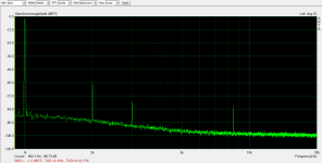

I don't know why that graphic is sideways. I edited/rotated/saved on my computer before uploading. No idea how to fix that since it displays properly on my computer.
Also, the peak in the spectrum at ~8.5kHz is a measurement setup artifact, not something in the amp output.
Also, the peak in the spectrum at ~8.5kHz is a measurement setup artifact, not something in the amp output.
I am not sure I understand the question (or the circuit). Are the undesirable AC currents power supply ripple?
"I'm trying to avoid extra time constants as much as possible in both of these solutions." does this mean you do not want a capacitor in series with the feedback loop?
"I'm trying to avoid extra time constants as much as possible in both of these solutions." does this mean you do not want a capacitor in series with the feedback loop?
I am not sure I understand the question (or the circuit). Are the undesirable AC currents power supply ripple?
"I'm trying to avoid extra time constants as much as possible in both of these solutions." does this mean you do not want a capacitor in series with the feedback loop?
The undesirable AC currents come from two places: 1) plate current variations in the driver when the plate voltage swings. This is minimized by having a CCS plate load with high-value resistor in parallel, but there is still a swing of ~.04mA with the 6384 output tube, which will increase to ~0.12mA with the DHT transmitter tube I eventually want to use and 2) screen current variations in the driver tube, which come out the cathode. These currents go into the feedback network and cause errors in the feedback.
I don't know how to quantify how much system-level distortion these AC currents cause, and so I will build circuit A) and test. It may turn out that I don't get a significant reduction in distortion or even an increase if I eliminate distortion that was cancelling with other distortion in the system. I can't wait to find out. The results are already pretty good but I'll always take better results if I can get them.
I'm just kicking around ideas and soliciting more if anyone can think of a better way than what I have come up with.
And yes you are correct that I don't want more capacitive coupling in the feedback path if I can help it.
What does the FFT look like from 0 to 1khz?
Steve
I didn't pay close attention to it as my measurement setup has its own artifacts down there and this is a breadboard amp with less than ideal grounding already.
I can tell you that I hear no audible 60/120Hz out of some pretty sensitive test speakers so that's a good sign.
I am using a Maida-style regulator for the B+, so I don't expect much ripple if any at the plate supply of the two tubes. This was always part of my plan for an SE amp because of the poor expected PSRR.
However, I think this circuit could make a pretty good push-pull amp as well.
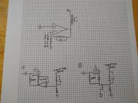
Upon further reflection, I'm not liking the diode in series with the p-channel follower driving the cathode of the 6BN11.
I've been using cathode bias on the 6BN11 stage to give extra bias stability, which I'm concerned about with such high gain in that stage, but diodes aren't going to help me in any way with that. Gain is over 700 in that stage so it wouldn't take much drift to have a big effect on plate voltage. Still, my experiments with this stage with cathode bias show that to be reasonably stable.
If I were to go this route for implementation, I think I'd just apply a positive bias voltage directly to grid through the 200k resistor. If it ends up drifting a lot, I have a bias servo board that I designed and works well that could be put to use on this.
I'll attach a picture later when I have some time to sketch it out.
Here's a picture. I'm hoping to be able to piece this together this weekend with parts that I have laying around. I've got a p-channel mosfet on a heatsink, just have to build an adjustable grid bias supply that'll cover the right range...
Attachments

Interesting stuff. is this local FB in addition to global FB?
Andy.
I'm not planning on any global feedback loop for this amp. I'm thinking it would be difficult to get good performance with the limited bandwidth that a cheap SE output transformer offers.
However, there is no reason you couldn't do that if you apply this to a push-pull amp or maybe with a top quality SE transformer.
This is local feedback but encompassing two stages rather than just a single one. What is driving me to this solution is that the output tube I want to use (826) doesn't have very much transconductance so even with 100% single-stage local feedback it won't quite make the performance level I want to see. If I go with a feedback loop that is a little less local but still doesn't go around the output transformer it treats the two stages as a single unit and I can use a high-gain input stage to get higher overall transconductance between the two stages. This will translate to lower Zout and distortion on the SE transformer primary than I could achieve with 100% feedback around just the output stage.
I've already seen that in my test results. With ~94% local output stage feedback, I got 0.29% distortion at 1W and over 1 Ohm Zout with the 6384 output tube. With this approach (without the improvements I have proposed above) I have already achieved 0.14% distortion at 1W and 0.8 Ohm Zout. This is with a 6384 output tube, but the principles should apply when I finally switch things over.
So what I'm trying to accomplish with this next experiment is to quantify some known shortcomings in my feedback network in this topology. If putting the p-channel fet or op amp driver into the cathode of the input tube cuts distortion of the system in half, I'll probably build that into the final solution. If improvement is negligible, I won't bother.
Forgot to add, I strongly suspect that this modification (buffering the input tube cathode) will result in a substantial improvement.
When I swapped in the 6BN11, I measured the open-loop gain of the input stage at over 700. The 6EW6 that I replaced had an open-loop gain of ~550.
Higher gain in the input stage should have resulted in lower distortion since there would be more feedback applied. However I measured pretty much exactly the same distortion before and after, 0.14% at 1W in both cases.
I suspect that the reason distortion isn't going down is the AC currents in the feedback network cause by plate/screen current swings in the input stage are dominating once I get down to a certain level of distortion.
We'll see if I'm right or wrong when I build and test. I rounded up all the parts to test the p-channel fet version yesterday so maybe with a bit of luck I'll have results this weekend.
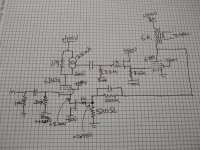
I redrew the whole amplifier so it is clearer what I'm doing here.
I did get the alterations done yesterday and did some limited testing on the input stage (6384 tube removed).
Before the p-channel fet was installed, the input stage was giving gain of about 720. Now it is giving gain of about 2600. Frankly, gain of 2600 kind of scares me.
Bias drift is a problem. I watched the plate drift ~100V over the first four minutes or so. After that, it seemed more stable. This is a significant drawback, but can be solved with a bias servo. I was already planning one for the output stage, what's one more?
Hopefully I'll have time for more testing soon.
Attachments
I'm sticking with distortion results at 1W for now, since it is exhausting doing a full series of measurements for every modification.
I've attached results for the primary and secondary of the output transformer. It looks like the transformer adds a little bit of 2nd harmonic at this level.
0.034% on the primary
0.046% on the secondary
I was curious if I would see any rise in higher order harmonics with the higher feedback ratio but I did not. Only 2nd and 3rd are above the noise floor and 2nd dominates.
Next I'll check some square waves to see if there is any ringing and measure Zout. I'm pretty happy with these results so far.
Attachments
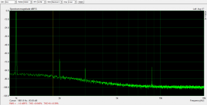
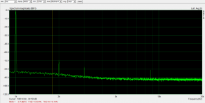
It's hard not to be pleased with those results. I be the noise floor is nice and low too on the other end of that FFT shot.
It's hard not to be pleased with those results. I be the noise floor is nice and low too on the other end of that FFT shot.
Yeah, I'm pretty happy about it.
My test setup is a high-impedance version of Pete Millett's soundcard adapter and an M-Audio USB sound card. I altered the design to make it run with scope probes. It's not the best as far as noise floor and is prone to pick up signals. I've never been able to make that ~8.5k peak go away except by switching ranges and making it disappear in the noise.
My noise measurements are a little less technical. I've got a pair of Sansui SP-200s in the garage that are pretty efficient and that I picked up at a local antique store for $30. So far, background hiss has been barely audible up close, which is probably a better result than the push-pull amps I have built. I'll have to do an A/B comparison later. But unfortunately, I don't have a good setup yet to really measure noise floor.
I guess that's okay. In the end, my design requirement is that I just want it to be pretty quiet with efficient speakers. I have the means to test that, just no numbers to brag about.
Zout results are in: 0.6 Ohms
Not bad, especially considering output transformer copper losses account for ~0.55 Ohms of that.
Not bad, especially considering output transformer copper losses account for ~0.55 Ohms of that.
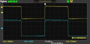
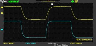
Low level square waves at 1kHz and 10kHz. Waveform on OT primary and secondary shown.
No signs of bad behavior. I've got 12pF in parallel with the feedback resistor right now, which can probably be reduced but I'll probably leave as-is until I get the transmitting triode worked into the circuit.
No signs of bad behavior. I've got 12pF in parallel with the feedback resistor right now, which can probably be reduced but I'll probably leave as-is until I get the transmitting triode worked into the circuit.
Attachments
Show-off ! 😀
OK, I'm envious. The stuff I build won't get within a light year of those results!
I hope you post what you hear. I'm eager to hear how you like it after a few months listening
OK, I'm envious. The stuff I build won't get within a light year of those results!
I hope you post what you hear. I'm eager to hear how you like it after a few months listening
- Home
- Amplifiers
- Tubes / Valves
- Output tube plate to driver cathode feedback