Hi all hope somebody can help ..... I am after a schematic layout for this built up board ...... the reason is I have 24v transformer and I want to connect it so that I have +30v and ground. Presently this board is designed to give +VE and -VE and ground. If I connect AC and ground it works but I am only getting something like 1/4 wave rectification. I want to cut the boards tracks and re connect the -VE bank so that it works as positive.......... the transformer would then connect to each AC input but not ground....
The problem I have is this is dual layer circuit board .... so has anybody built one of these and can they help regarding a general schematic...

https://oi1064.photobucket.com/albums/u367/D3savage/Top again_zpsnkkeg3kj.jpg?t=1594110071
https://oi1064.photobucket.com/albums/u367/D3savage/Top Left_zpsyh7bgqkz.jpg?t=1594110096

The problem I have is this is dual layer circuit board .... so has anybody built one of these and can they help regarding a general schematic...
An externally hosted image should be here but it was not working when we last tested it.
An externally hosted image should be here but it was not working when we last tested it.
https://oi1064.photobucket.com/albums/u367/D3savage/Top again_zpsnkkeg3kj.jpg?t=1594110071
https://oi1064.photobucket.com/albums/u367/D3savage/Top Left_zpsyh7bgqkz.jpg?t=1594110096


...I am only getting something like 1/4 wave rectification.....
Interesting??

The connection below is full-wave. Simply *ignore* the "GND" terminals. As-made, it has to be loaded-up with twice as many 25V caps as you would need with a simpler plan with half as many 50V caps. It is not hard to wire this up without a PCB. However since you are not clear, just do it this way. If it is already full of >24V caps, you are good to go.
Attachments

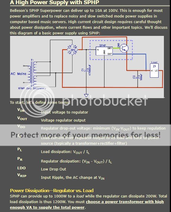
Hi here is the circuit ..... the issue I have is that I have a Belleson SPHP positive regulator 19v ...... my transformer is 12 0 12 so if I connect the windings on traffo I get 24v ac.
What my regulator needs is + and ground I don't need -vee side and I could do with isolating -vee capacitors and using them for +vee I am not sure about rectifier I need to make full use of rectification not 1/4 wave.
If I connect as you suggest I will get + 26v rms (ish) and -26v rms approx 52v my regulator will not accept -vee see diagram below....
https://oi1064.photobucket.com/albums/u367/D3savage/Belleson SPHP_zpsbjwbks8x.jpg
An externally hosted image should be here but it was not working when we last tested it.

Hi I have just seen your clip ..... will my regulator go splat if I connect it Vee- (ground)??? Sorry bit of a noobie ...... just do not want to destroy a good regulator ....
Last edited:
I'm not sure you need all those when you use that regulated psu.
The cap bank will draw a lot of current until its charged, could damage the regulator
The cap bank will draw a lot of current until its charged, could damage the regulator
The regulator is fitted to the output of this supply ..... just using this as a nice smooth low ripple supply to supply the super regulator....see the blleson sketch
https://hosting.photobucket.com/albums/u367/D3savage/Belleson SPHP_zpsbjwbks8x.jpg
https://hosting.photobucket.com/albums/u367/D3savage/Belleson SPHP_zpsbjwbks8x.jpg
- Home
- Amplifiers
- Power Supplies
- LJM Ebay PSU 68 capacitor help required