Thanks gglera. Nice clean build. I also like that you used the sides of the enclosure as a heat sink. Its nice that these amps don't need a huge heatsink, although I always seem to use a big one anyway. I remember the heatsink on Dario's development board was just a piece of aluminum sheet.
Jac
Yeah Jac, I think next one I build isn’t going to use heatsinks. I’ll just use the sides of the chassis (like gglera) and save on space&weight.
Pete
It will work.
Watch the temperature. If it heats up too much stick a CPU cooler to the side of the chassis. My FE has no heatsinks too. Stick on finned heatsinks.
Yeah Jac, I think next one I build isn’t going to use heatsinks. I’ll just use the sides of the chassis (like gglera) and save on space&weight.
Pete
Watch the temperature. If it heats up too much stick a CPU cooler to the side of the chassis. My FE has no heatsinks too. Stick on finned heatsinks.
I have build myref in 2015 and really enjoyed it. Since then I have moved places and somewhat abandoned the hobby, disassembled speakers and put away components. But I vividly remember how myref opened up possibilities in music and how much more I could hear in each and every song. I will get to upload some pictures, especially then I have decided to resurrect the system.
On the other hand, a lot of reading to do on what has changed in the design philosophy of myref since 2015
On the other hand, a lot of reading to do on what has changed in the design philosophy of myref since 2015
A little OT
With this last 14th GB grand total of My_Ref FE stereo kits (beta and release candidate boards excluded) will be over 500!

With this last 14th GB grand total of My_Ref FE stereo kits (beta and release candidate boards excluded) will be over 500!
With this last 14th GB grand total of My_Ref FE stereo kits (beta and release candidate boards excluded) will be over 500!
Thank you Dario,
This ongoing project has provided many with a lot of knowledge and also a very accurate amplifier. Looking forward to building the next one.
On the other hand, a lot of reading to do on what has changed in the design philosophy of myref since 2015
Hey vox, good to hear from you again.
The amazing thing is that the basic design hasn't changed, it is just been refined as small changes improve the design and as people try new components. The only philosophical change is an unofficial branch where George has explored jfet opamps that lead to different compensation and different sound. The FE circuit diagram is basically the same.
That said, a change in layout for v1.5 made a noticeable improvement in noise and, based on that, Dario reimagined the BOM to improve neutrality and reduce cost. This current GB is another step with Dario selectively reviewing the BOM and making room for new component choices.
Welcome back.
Jac
With this last 14th GB grand total of My_Ref FE stereo kits (beta and release candidate boards excluded) will be over 500!
Not off topic at all. Let's celebrate!!
Hey vox, good to hear from you again.
Jac
Hi again.
To be fair it was a bumpy ride (2020 excluding) . Changed two professions, enrolled to uni. Got into board gaming and endurance racing. Now it is time to go back to music.
Thanks for a heads up, I need some time to understand a current state of the diy and possibly proceed with a bottleneck- upgrade speakers( to fully engage such an incredible amplifier). My seas er18rnx and seas 27 dxt combo, although sounding really good is not revealing enough.
P.S. If I am to upgrade from 2015 version to 1.5 what exactly to do with parts count? I am ok with researching it myself, just point towards any credible information so I do not have to read so many years of research and development history.
Last edited:
Endurance racing sounds fun. Back in the 80's, I was working for VW in the US and was allowed to provide engineering support for a low level endurance racing team. I'm sure these cars were at a much lower level than anything today, but I really enjoyed the strategy, the competition, and the camaraderie of endurance racing. In a season, we had two 24 hour, three 12 hour, and four 6 hours races, so I was also always tired.
First of all, the FE you built in 2015 is still an excellent amp. There is nothing you absolutely have to change. I am running a 4 channel FE amp with earlier components in one of my systems and it sounds fine. In fact, I played around with different dacs and found more improvement in sound than the improvement between my older 4 channel and my newer FE in my main system.
One main difference between pre and post v1.5 was in the board arrangement. The location of R11 was changed to reduce noise and the difference can be seen in the KSTR (early board) vs Joseph K (later board) measurements shown in the first post of the GB thread.
My_Ref Fremen Edition GB (14th GB)
On the same page, you can get to Dario's FE Google Drive that has early and late BOMs. A couple of things to note. C1 and C2 have been bumped up to 470 uF from 220. You can make this change on the old boards as long as you pay attention to lead spacing and diameter, but you might not hear a huge difference. Also, the "Evo Rev A Mod" is now being used universally and can be easily achieved on an older board. This doesn't provide any major change in sound but does improve stability. The through hole resistors have been changed to mostly Dale RN55. This changes the sound to cleaner and more neutral, but some say slightly less warmth.
The most recent board (GB 14) is making room for a TO-247 resistor in R3. The Caddock usually used there is good, but not as clear as some alternatives. A good wire wound resistor mounted soldier style is one option. The TO-247 options are a group of Manganin resistors that people have been trying. BTW, you can make the TO-247 resistors work on existing boards, its just not very pretty.
Another option for R3 is something I have been trying. You can read about it in post #3704 of the FE Build Thread and search my user name or "quad" for other posts. I have yet to compare to the Manganin resistors, but hope to soon.
Finally, the unofficial jfet opamp approach is something that Joseph K (George) came up with. You can read about that starting at post #3078 and running through about #3150 of the Build Thread. There are also later posts as this is an ongoing development. As a matter of fact, I think he is playing with a new opamp as I write this.
Have fun with your music.
Jac
Last edited:
Thanks Jac.
I will get to reconciling what to do next after camping trip. First-ever after lock down.
I will get to reconciling what to do next after camping trip. First-ever after lock down.
P.S. If I am to upgrade from 2015 version to 1.5 what exactly to do with parts count?
I will add to Jac answer:
For pre-1.5 boards is available an updated BOM to align component selection to later BOMs.
A real upgrade to 1.5 distortion performance cannot be achieved with the updated BOM, though.
You hower going in the righ direction see post My_Ref Fremen Edition - Build thread and tutorial
the FE you built in 2015 is still an excellent amp. There is nothing you absolutely have to change. Have fun with your music.
Jac
I just built up a V1.05 set of boards using the most moderne BOM for the Evo A mod and it’s still a fantastic sounding amp. See my earlier post. R3 makes a huge impact on the sound even with less-than-audiophile components. George’s op-amp mods are a marvelous path to try.
I will add to Jac answer:
You hower going in the righ direction see post My_Ref Fremen Edition - Build thread and tutorial
Thanks!
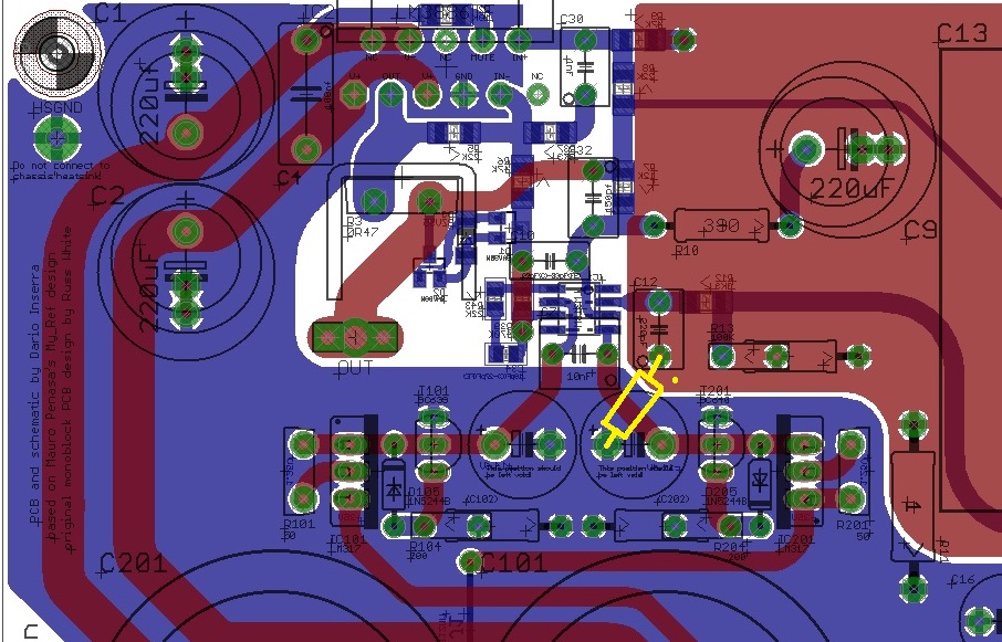
R11
Dario, et al., so for the V1.05 boards I just built should I follow the picture above and move R11 from its current position on my board (near C13) and move it to the position shown in the diagram Dario posted, from the "+" lead side of the empty cap to C12?
Thanks, Pete
The latter boards (from 1.5 and Up) have tenfold less distortion and most of this reduction is due to R11 position.
Dario, et al., so for the V1.05 boards I just built should I follow the picture above and move R11 from its current position on my board (near C13) and move it to the position shown in the diagram Dario posted, from the "+" lead side of the empty cap to C12?
Thanks, Pete
This thread was created for posting photos and reviews.
Please follow this thread to discuss board design and other questions:
My_Ref Fremen Edition - Build thread and tutorial
Thank you for understanding. Wish a good day for all 🙂
Please follow this thread to discuss board design and other questions:
My_Ref Fremen Edition - Build thread and tutorial
Thank you for understanding. Wish a good day for all 🙂
Stream is right. It is easier to find build related things if they are all in the Build Thread. Alas, I/we are not always a very disciplined group. Back to the Build Thread we go.
Yes, I understand the concept, but this is where Dario posted the picture which is why I asked the question in this thread. I figured if he put it here w/o correction my question would be OK here as well.
Pete
Pete
Stream is right. It is easier to find build related things if they are all in the Build Thread. Alas, I/we are not always a very disciplined group. Back to the Build Thread we go.
...and no disrespect meant to either Stream or Jac for the corrective comments on etiquette. My apologies if my response sounded terse.
Pete
No problem. We all just fall into it. Hey, this is an easy group or at least I hope it is. Just think about how tolerant of off topic Dario has been. I hope I am the same, but an occasional nudge back on course can be useful.
Jac
Jac
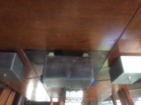
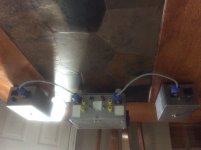
My FE build
This uses the boards from the 13th group buy. The three chassis from another project.
Powercon connectors from transformers. Amphenol Mil-Spec BNC Twinaxial input connectors. EF Johnson 5 ways. Brass power transformer mounting bolts.
This uses the boards from the 13th group buy. The three chassis from another project.
Powercon connectors from transformers. Amphenol Mil-Spec BNC Twinaxial input connectors. EF Johnson 5 ways. Brass power transformer mounting bolts.
Attachments
- Home
- Amplifiers
- Chip Amps
- Fremen Edition My_Ref Amplifier – Completed Projects and Photos