Doesn't seem like the MJK worksheets are the way to go anymore, is Hornresp now carrying the torch? Between that and Akabak, which one would be easier to learn for a noob?
Are there any case studies of a simple nature that shows the differencies between mltl and normal vented boxes?
Don't know about any case studies but it's rather straight forward. The longer or taller an internal cabinet dimension is, like its height, the more contribution to the system tuning from that dimension's 1/4-wavelength resonant frequency, while the port makes up for the remaining tuning based on the volume in the line. An advantage of modeling a tall, vented box as an ML-TL is that the port's location can be optimized relative to the driver's location, leading to the smoothest overall response shape. Software for vented boxes, AFAIK, don't/can't take into account cabinet dimensions or driver and port locations, determining the port's dimensions based only on the cabinet's volume.
Paul
Paul
Are there any case studies of a simple nature that shows the differencies between mltl and normal vented boxes?
From what I understand, unless your sub is a cube shape, an MLTL model will typically be more accurate than a simple vented model, especially as the frequencies get into the 100s of Hz.Are there any case studies of a simple nature that shows the differencies between mltl and normal vented boxes?
The straightforward way of looking at it is this. A typical vented box derived from a Helmholtz basis assumes a uniform internal air-particle density and no standing waves to be present. The point of transition to an ML quarter-wave can be said to occur when you stretch one dimension sufficiently for the longitudial eigenmode to alter the alignment away from what you would obtain from a regular vented box of the same volume & vent dimensions using purely Helmholtz based assumptions.
A BR works if the ratios of the dimensions do not become too large
As one dimension becomes considerably larger than the others a BR transitions to a Mass Loaded TL.
Compilation of MJK ANSYS simulation of BR vrs ML-Voigt (an ML-TL variant).

As length increases the line frequency goes down, and the frequencies that exit the terminus is lower.
You can also use Leonard SW freeware to sim TLs.
dave
As one dimension becomes considerably larger than the others a BR transitions to a Mass Loaded TL.
Compilation of MJK ANSYS simulation of BR vrs ML-Voigt (an ML-TL variant).
As length increases the line frequency goes down, and the frequencies that exit the terminus is lower.
You can also use Leonard SW freeware to sim TLs.
dave
Practically speaking, point taken. Literally though I would question that it may be the dimensions itself. Would an elongated cabinet behave this way if no dimension approaches 1/4 wavelength in the vicinity of the primary resonance?A BR works if the ratios of the dimensions do not become too large
Well, that rather depends how you look at it. What you're describing would be what GM and I would loosely define a 'real' MLTL, where the longitudinal standing wave progressively damps the vent at tuning, so you need to make adjustments to maintain the same Fb vis-a-vis pure Helmholtz derivations. However, most MLTLs aren't quite so strictly defined, so while that longitudinal eigenmode may affect the alignment, it isn't necessarily coinciding with what would be the nominal cavity Fb.
So, for one that can only simulate a standard/normal vented box but want a floorstanding box, like a high and narrow two way design, where should one put the driver and the vent so the simulation still holds true? Or, where should one place the driver and the vent for maximum deviation from the simulation?
If the box has one dimension significantly stretched relative to the others, the simulation (as in a simple Helmholtz derivation) is unlikely to hold true to some degree or other no matter where you locate the vent & driver. Those only have a major impact upon the pipe harmonic modes; the fundamental is relatively unaffected by this. If you want maximum deviation, driver & vent together at one end. That'll do it. 😉
Speaking generally, how much deviation you get from a Helmholtz based assumtion ultimately depends on the aspect ratio of the box. If you want to avoid the longitudinal mode affecting things, you either need to break it up or absorb it. That's why a lot of good tower designs have a significant amount of damping material at the bottom. Not strictly speaking the most effective place to locate it, but usually the most practical from a construction POV, and since damping material usually isn't over expensive,a bit extra isn't likely to bust the piggybank. There are other ways, but that's usually the most straightforward.
Speaking generally, how much deviation you get from a Helmholtz based assumtion ultimately depends on the aspect ratio of the box. If you want to avoid the longitudinal mode affecting things, you either need to break it up or absorb it. That's why a lot of good tower designs have a significant amount of damping material at the bottom. Not strictly speaking the most effective place to locate it, but usually the most practical from a construction POV, and since damping material usually isn't over expensive,a bit extra isn't likely to bust the piggybank. There are other ways, but that's usually the most straightforward.
Last edited:
So basically, we have software that can model a crossover for 5way speaker and software that does waveguides with whatever curve, profile or size that derives files for 3D print but there is no software available to calculate mltl and port position accurately ?
Hahaha
Hahaha
Last edited:
Far from it. Martin's worksheets and George Augspuger's TLwrx are NLA, but (for example) Hornresp, the Leonard Audio TL software, Akabak and AJhorn can all model MLTLs if you wish to do so.
Last edited:
I believe a basic helmholz simulation should use an infinitely small cone, box and vent located in the same point in space (for all modal considerations).
As I see it, whether the result would be considered 'significantly' minimum phase and hence subject to standard Helmholtz analysis is going to have a connection to the amount of travel, elongated or otherwise, in comparison to wavelengths of interest.Scottmoose said:If you want to avoid the longitudinal mode affecting things, you either need to break it up or absorb it.
Exactly. It's not like there's a specific 'one-size-fits-all' transition, it ultimately depends on the design in question & what you're doing.
I believe a basic helmholz simulation should use an infinitely small cone, box and vent located in the same point in space (for all modal considerations).
In Hornresp, the driver's specs are irrelevant to getting an accurate reflex/BR or band-stop filter vent calculation for a given Vb, which BTW the driver/vent is at the same point in space, so presume this is true for any [accurate] basic BR calculator.
GM
Apologies, I was thinking internal modes.
Re driver / vent, as far as I know. At any rate, I don't recall seeing any basic BR caculators that don't assume a coincident radiating point for driver / vent; you've got to shift to something like Basta for that. I haven't got VituixCAD loaded at the moment so I can't check if it can (never needed to use its box modeller so don't know off-hand).
Re driver / vent, as far as I know. At any rate, I don't recall seeing any basic BR caculators that don't assume a coincident radiating point for driver / vent; you've got to shift to something like Basta for that. I haven't got VituixCAD loaded at the moment so I can't check if it can (never needed to use its box modeller so don't know off-hand).
which BTW the driver/vent is at the same point in space
Just to clarify, in Hornresp the above only applies if the acoustic path length parameter value is set to zero.
Attachments
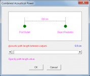

So I forgot to say the 'default' is..... 😉 Frankly, I've yet to see anyone's basic BR sim where they take advantage of it but me.
GM
GM
- Home
- Loudspeakers
- Multi-Way
- Modeling MLTLs nowadays