Dear Guys
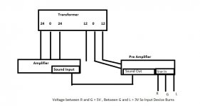
I am trying to assemble my own amplifier using a amplifier board and a pre-amplifier board i bought. My amplifier board is based on 4 C3280 transistors (works on 24ac-0-24ac , and pre amp 12ac-0. Both boards are working fine. My Pre-amplifier is based on LM1036. I gave pre-amp out directly to amp input. But when i try to connect mp3 player to pre amp input, it burnt. I checked the in line voltage of the pre-amp. it goes over 5V. What could be the issue here, please hep. I already burned two mp3 players trying to connect as input sources so far . This is my first Electronic project of this kind. Please find the block diagram of my design
 . Please help me to identify the issue here. Thank you.
I am trying to assemble my own amplifier using a amplifier board and a pre-amplifier board i bought. My amplifier board is based on 4 C3280 transistors (works on 24ac-0-24ac , and pre amp 12ac-0. Both boards are working fine. My Pre-amplifier is based on LM1036. I gave pre-amp out directly to amp input. But when i try to connect mp3 player to pre amp input, it burnt. I checked the in line voltage of the pre-amp. it goes over 5V. What could be the issue here, please hep. I already burned two mp3 players trying to connect as input sources so far
. This is my first Electronic project of this kind. Please find the block diagram of my design
To attach images, always Go Advanced and upload directly.
Do these excessively high voltages at the input disappear when the connection between preamp and power amp is removed? I kind of doubt it.
Sounds like a problem with the preamp board tbh. I suspect it's finest AliExpress quality? Check whether there are any input coupling capacitors at all (they are required), and if so, whether they are installed correctly (- side goes to input, + side to pin2/19).
All that is assuming that the 12V~ winding is in fact completely separate (galvanically isolated) from the 2x 24V~.
Thank you for your prompt response. Please find the link to the Image. Can you please explain me what type of capacitor i need to add and to which wires i need to connect it. Design — ImgBB
> Click the image to open in full size.
Images posted on an EXternal host now must be opened with Right-Click and "Open in New Tab".
Both of sbrsus' external links seem to be the same image? Attached ON this forum:
Unfortunately, it does not open)))
Images posted on an EXternal host now must be opened with Right-Click and "Open in New Tab".
Both of sbrsus' external links seem to be the same image? Attached ON this forum:
Attachments
Is the preamp power supply unipolar or bipolar?AC or DC? What's in the manual?
According to your scheme, it turns out 12 v AC (transformer)?
According to your scheme, it turns out 12 v AC (transformer)?
Thank you for your prompt response. Please find the link to the Image. Can you please explain me what type of capacitor i need to add and to which wires i need to connect it. Design — ImgBB
Insert non-polar capacitors 470n between each input (R and L) and source.
Preamplifier and Amplifier connected by three wires - R-G-L?
I noticed that normally voltage at one end of the 0.1uf capacitor is 4.5V and output end(which goes to input line directly) it stays 2.5V. When i switch on or off the unit voltage surge to 4.5V and slowly going down to 2V . Does this mean the capacitors are bad ?
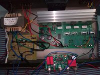
Bizarre.Yes You are absolutely right. The input voltage disappear when the connection between pre amp and power amp is removed. Please find the image of the assembled amp. Is there anything that I can do to make it work ?
For one thing, I would make sure that your transformer actually has separate, galvanically isolated 2x 24V~ and 2x 12V~ windings by measuring resistance between them with the multimeter. You should be seeing something way in the Megohms, or even OL (open). I have my doubts though, as I'm only seeing 5 secondary-side connections, and 2x (V~ - CT - V~) inevitably requires 6.
Things can be made to work if they share a common center tap, but some more care is required then. Check whether one AC input terminal of the LM1036 board is connected to its ground; if so, that's where the center tap has to go.
That's not where your worries stop though, as even if you can make things work you may still have to fight ground loops. It may be easiest to obtain another small transformer just to feed the LM1036 (3 VA should be plenty).
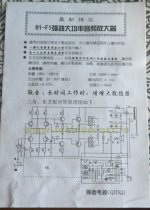
Google tells me that WG-9909 may be the amplifier reviewed here, so a basic complementary input Rotel-style circuit with EF2 output and terrible R + D biasing (which ideally is best replaced with a real bias spreader using a TO-126 mounted to the heatsink). With an onboard bridge rectifier, it takes the usual center-tapped secondary, nothing unusual about that.Please link to amp and preamp pages so we are a little less blind.
The LM1036 board labeled "DX001" seems to be up on AliExpress under various brand names, e.g. this one. No indication of any schematic or how the rectifier would be wired up to the AC input - I can think of two versions.
Attachments
Power access 12v AC/DC: Bridge,10000mk 50v, 7812. Lm1036 with disassembly.
Treble Bass Volume Control. Connectors Input/Output -3pin, Power -2pin.
Zero is grounding. 12v AC or DC about "0".
Check the performance of the board separately.
Treble Bass Volume Control. Connectors Input/Output -3pin, Power -2pin.
Zero is grounding. 12v AC or DC about "0".
Check the performance of the board separately.
Finally found the issue. I powered the pre amp circuit using a separate 12v transformer, issue is resolved. Everything is working perfectly. Thank you all for your valuable advices. 
- Home
- Amplifiers
- Solid State
- High Voltage Back to Pre Amp Input source