Input Impedance: 33 k Ω
Well, that makes life easier!
OK, so 1uF would do fine for an f3 of about 5Hz.
2.2uF would get you down to 2.2Hz or so.
1uF 400V is very common. Just about any poly-something film cap would have much less DC leakage than the 10uF electrolytic.
There ya go!
Sorry but no. If you had read the full thread or at least the 4 or 5 posts above yours you would have learned that:
has as much "sand" as you would find in an average beach")
Yes the fine art of reading
Why people want to change something that has little to do with the issue is beyond my understanding. Changing values of output caps will not solve stuff. Shorting outputs to GND while warming up is THE solution for voltage spikes that trigger sandamps and it makes operation with sand amps safe as explained.
Last edited:
A reasonable dimensioning of output caps and load resistor prevents buildupYes the fine art of reading
of unwanted voltages.
Using unreasonable large caps will create problems, and this without any
audible benefits, in addition introducing electrolytic caps in the signal path.
Note that both available sources of music is limited to way above 20hz,
owners speakers might be negativly affected with subsonic power, and
sure enough few speakers are capable of dealing with 20hz. Why then
try to pass these signals to the poweramp ?
Adding extra relays and associated electronics will not enhance reliability.
Adding extra relays and associated electronics will not enhance reliability.
In a tube preamp from China the added single relay killing the chances for a high voltage DC spike at the outputs at power on/off may just be the only reliable thing to protect the amplifier
Besides that the relay is shorting outputs to GND so when it fails it is not an added risk at all as the outputs stay muted. Easily diagnosed too I guess 2020 is too early for muting. Anyway both the OP and Jviz4u in post #42 DO have semiconductor amplifiers that are killed quite easily with relatively low voltages (in the eyes of tube people) so what is the point of trying to win the discussion?
Last edited:
The point is to NOT transmit unneeded surges to the power amp. ThisIn a tube preamp from China the added single relay killing the chances for a high voltage DC spike at the outputs at power on/off may just be the only reliable thing to protect the amplifier
I guess 2020 is too early for muting. Anyway both the OP and Jviz4u in post #42 DO have semiconductor amplifiers that are killed quite easily with relatively low voltages (in the eyes of tube people) so what is the point of trying to win the discussion?
by dimensioning output caps to be discharged faster then the B+ rises thus
preventing them to occur. ( B+ will rise slow even with a Si rectifier)
This fulfills a good engineering principle; make it right instead of adding kludges to solve
what was wrong.
If that won't filter out any audible frequency's what is the problem ?
Last edited:
A possible issue that may damage sensitive stuff is best solved at the root. When no voltage can occur I would call that relatively safe. It is standard practice in any quality audio source device. The point being to make it practically impossible to transmit power on/off surge voltages to the outputs regardless of output cap value.
Last edited:
I aggree.A possible issue that may damage sensitive stuff is best solved at the root. When no voltage can occur I would call that relatively safe. It is standard practice in any quality audio source device. The point being that it is impossible to transmit any power on/off phenomenon to the outputs regardless of output cap value.
My suggestion is to make the design so it won't occur. Your suggestion is
to add devices to short it out and try to make this fault-proof.
( what happens with your device when the preamp is powered down while
the poweramp is powered on. Will it block then too ? Or will it transmit
a possibly damaging surge ?)
A slow turn on/fast turn off muting circuit is meant to short preamp output every fast at power off eliminating any nasty surge (audible and/or damaging). It cancels the silly prescribed power on sequence that no family member will do the right way too making the device practically foolproof. Way better to keep marriages OK and children happy.
It is a novelty and therefor hard to swallow for some but it will be big some day
It is a novelty and therefor hard to swallow for some but it will be big some day
Last edited:
The turn off muting have to be detect poweroff fast, before B+ has been reduced more then a few %, and at the same time it mustA slow turn on/fast turn off muting circuit is meant to short preamp output every fast at power off eliminating any nasty surge (audible and/or damaging). It cancels the silly prescribed power on sequence that no family member will do the right way too making the device practically foolproof. Way better to keep marriages OK and children happy.
It is a novelty and therefor hard to swallow for some but it will be big some day
not react for spurious noice not to short the signal erroneously.
This can be a challenge.
I would still suggest a design where no such device is needed and no problem
with surges may occur. In addition no electrolytic caps are in the signal way.
Why transfer signal information that does not add to the sonic qualities ?
Why not filter at the source instead of add a kludge ?
I guess we stop here we seem to repeat ourselfs, let others continue this
discussion.
You ask some things and then suggest to stop the discussion. A bog standard muting circuit with a relay will put nothing in the signal path. It is no challenge to design such a circuit. There are plenty examples to be found how to implement this. Many Japanese quality audio devices can be used for an example. Elektor also used these circuits extensively in DAC designs etc.
I consider any source device without this an unsafe device for my amplifiers and speakers and I refuse to connect such flawed gear. Just as I refuse to use power amplifiers that have no protection circuit against power on/off surges and DC.
I consider any source device without this an unsafe device for my amplifiers and speakers and I refuse to connect such flawed gear. Just as I refuse to use power amplifiers that have no protection circuit against power on/off surges and DC.
The electrolytic cap IS in the signal path. Remember ? Some folks willYou ask some things and then suggest to stop the discussion. A bog standard muting circuit with a relay will put nothing in the signal path. It is no challenge to design such a circuit. There are plenty examples to be found how to implement this. Many Japanese quality audio devices can be used for an example. Elektor also used these circuits extensively in DAC designs etc.
I consider any source device without this an unsafe device for my amplifiers and speakers and I refuse to connect such flawed gear. Just as I refuse to use power amplifiers that have no protection circuit against power on/off surges and DC.
avoiud using electrolytic in signal path. My suggestion is to replace
with a plastic folie cap. ( in the process of this redisign it will also
remove the ability to emit surges, thus make the relay and associated circutry
uneeded)
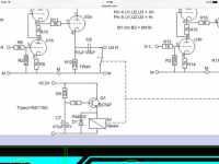
Again i aggree.Example from post #10. No sound thinking person uses electrolytic caps in the signal path when it is not absolutely necessary.
The amp in questing ( chinese kit) uses a electrolytic can of 10uF. Not
an expensive 10uF folie cap.
Schematic in post #1 (and in the picture) has a film cap. Does not make a difference in the light of the lengthy discussion we had.
Now back to the subject. Please. Let's build devices that are intrinsically safe, foolproof and easy to operate. For some reason I remind an amplifier that I once had that "remembered' the last volume setting. In case some family member had turned it to max and the wrong switched off source was selected this could lead to nasty surprises when I switched it on and selected the right source. Stupid design = stupid design.
Now back to the subject. Please. Let's build devices that are intrinsically safe, foolproof and easy to operate. For some reason I remind an amplifier that I once had that "remembered' the last volume setting. In case some family member had turned it to max and the wrong switched off source was selected this could lead to nasty surprises when I switched it on and selected the right source. Stupid design = stupid design.
Last edited:
Again, agree.Schematic in post #1 (and in the picture) has a film cap. Does not make a difference in the light of the lengthy discussion we had.
Now back to the subject. Please. Let's build devices that are intrinsically safe, foolproof and easy to operate.
Simple and faultproof foolproof and reliable.
My suggestion : by replacing one (1) component the above is true. At no loss
of fidelity.
Power supply caps are often in the signal path, so this isn't that crazy.Example from post #10. No sound thinking person uses electrolytic caps in the signal path when it is not absolutely necessary.
- Status
- This old topic is closed. If you want to reopen this topic, contact a moderator using the "Report Post" button.
- Home
- Amplifiers
- Tubes / Valves
- output of valve preamp showing a high voltage when turned on