In series with the resistor under the voltage regulator tube? I suspect the mosfet circuit ground can't be the same ground as the tube circuit's ground. It would be floating. If so I could use 2 12V zeners and the ground for the mosfet would be the middle of the two?
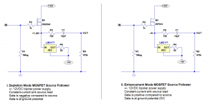
The ZVN0545A is a terrific part, but it's an enhancement mode device and will not self bias. 🙁 Use the ZVN0545A when it can be DC coupled to a thermionic device's plate. The requisite forward bias is a "no-brainer" under those conditions.
Thanks Eli, but I don't understand why an enhancement mode MOSFET won't find its bias if its gate is held at ground potential (0 volts) and its source has a CCS load with a negative voltage supply, as shown in the IRF510 schematic.
I'd think it wouldn't matter if the source is at a negative potential if the gate is at ground. That will provide the gate with a voltage that's positive compared to the source, which is what is required with the enhancement mode MOSFET.
True you'd have to use a JFET or depletion mode MOSFET with a source resistor for self-bias if you use a positive-only B+, so that the source will be at a positive potential compared to the gate.
However, with a bipolar supply, if I use a JFET or a depletion mode MOSFET with CCS in the source to B-, the depletion mode device will find its bias point with the source positive to the gate, the same as with a single-pole (positive only) B+.
Is the problem that an enhancement mode MOSFET or BJT will run away and self-immolate if used the way I showed in the IRF510 schematic? But then why would that work when DC coupling from the plate of a triode? What does it matter if the MOSFET gate is at 150VDC or 0VDC, as long as its source is -4V below its gate?
Am I missing something? I wouldn't be surprised if I am.
--
Last edited:
Out of the packaging, enhancement mode devices constitute open circuits. Applying a forward bias to the gate forces the channel open and current can then flow through the device. Enhancement mode devices need the "faucet" cracked open (forward bias) to function, while depletion mode devices, including tubes, need the "faucet" turned almost closed (reverse bias), lest destructive excessive current flow.
Without forward bias on the gate, an enhancement mode device will conduct (very briefly) only if its breakdown thresholds are exceeded.
Without forward bias on the gate, an enhancement mode device will conduct (very briefly) only if its breakdown thresholds are exceeded.
Oh well. There goes that 'brilliant' idea. Good thing I asked, eh? 😱
Fortunately, the DN2540 and DN2535 depletion mode MOSFETs are not expensive any more.
And thank you for the explanation. Obviously, I needed that!
Fortunately, the DN2540 and DN2535 depletion mode MOSFETs are not expensive any more.
And thank you for the explanation. Obviously, I needed that!
Last edited:
....run a ceramic cartridge turntable through some powered studio monitors....
Why??
Historically, ceramic carts were "cheap" relative to mag phono carts.
You've had some far-out suggestions for making the most of a ceramic, but what about the EQ? A naked displacement pickup needs a top-lift to play a standard record. But 90% of ceramic carts have an approximate correction built into the mechanicals (generally as a damped resonance in upper midrange).
Why ceramic is, indeed, a very interesting question.
1 of the many projects I hope to get to, before death claims me, involves a so called HIFI ceramic cartridge in my parts stash. Decca and some other folks made these devices that exhibit comparatively low O/P levels and a top frequency limit above 15 KHz. The specimen I have will track at 2 grams, which is similar to many LOMC items. With arm pillar buffering, I have a sneaking suspicion the "HIFI" ceramic device will require custom EQ in the preamp. Yes, gain is needed to raise the O/P to what is regarded as "line" level. FWIW, my cart. has "standard" 1/2 inch mounting ears.
I'm guessing the Astatic cartridge the OP mentioned produces an O/P in the vincinity of 0.5 V. Rochelle salt crystal cartridges produce volts, but track at record damaging forces. Crystal carts. also tend to go bad over time, as they pick up atmospheric moisture.
Why a ceramic cartridge?
I guess it is a steampunk thing. An odd mix of technologies, vintage and modern. If you have a RCA 45-j2 45rpm vintage record changer you have to play it through a crappy low power vintage AM American 5 radio, or some equivalent. I want to plug it into my Home Theater Amp (Line in) and blast a stack of old 45s.
In this case I want to play my 4 speed Panasonic RD7673 trough a set of modern JBL powered studio monitors. It does things no modern turntable will do, play 16, 33, 45 and 78 rpm and it is a record changer. (Every try to find a modern turntable with a record changer? They don't exist and believe it or not I have a large collection of 16rpm vinyl.) I suppose I could try to modify the tone arm to accept a MM but that opens a whole new can of worms.
The output of the Astati 713 is indeed 500mV so I need not just a buffer but a preamp section, but as posted above, I need no RIAA. As for the EQ issue, as a line level device, I can always use a graphic equalizer. The solution that came out of this thread looks very encouraging. Thanks to you all. I really want to have a tube pre-amp to try to get that vintage sound as much as possible. That is part of the reason for the 12SQ7 as buffers , commonly used in the old American 5. I need to triple the output so I think the 12AY7 will do nicely for gain, but I may find I will need a 12AX7? Since it will be line level out compatible, I should be able to play it on studio monitors or the Home Theater.
Last edited:
Out of the packaging, enhancement mode devices constitute open circuits. Applying a forward bias to the gate forces the channel open and current can then flow through the device. Enhancement mode devices need the "faucet" cracked open (forward bias) to function, while depletion mode devices, including tubes, need the "faucet" turned almost closed (reverse bias), lest destructive excessive current flow.
Without forward bias on the gate, an enhancement mode device will conduct (very briefly) only if its breakdown thresholds are exceeded.
Hi Eli,
Thanks for the great explanation of enhancement mode device gate threshold. The faucet metaphor lit the light bulb for me.
So then I thought of something (always a dangerous thing...):
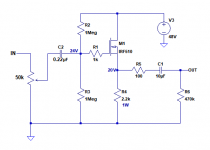
What about a simple voltage divider from B+ to create fixed bias for an enhancement mode MOSFET? Would fixed bias from a voltage divider set the conditions necessary to get the MOSFET conducting current? Like so (attached)...
[For the crystal pickup input buffer, remove the volume control, and perhaps change value of R2, R3 to 4.7M?]
[Would C2 present a problem for a crystal pickup?]
There are +48V 1A SMPS wall warts available for cheap. I'm sure a better power supply could be constructed, but for quick 'n cheap, this could be pretty good?
Attachments
Last edited:
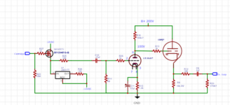
I am working on building a preamp/buffer based on the MOSFET and 12sq7 design we discussed, however I found this Mullard schematic:
Mullard Stereophonic Pre-amplifier
Can I get any comments on this design? It has "crystal" inputs. What would be the comparison between performance of the two designs? I could build this using the microgrove / 78 inputs.
Mullard Stereophonic Pre-amplifier
Can I get any comments on this design? It has "crystal" inputs. What would be the comparison between performance of the two designs? I could build this using the microgrove / 78 inputs.
Attachments
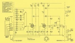
The mullard design seems to have a quite high output impedance, it was typical of the day.
In addition the tonecontrol network seems to be dependent of the poweramps
input impedance. A guess is that the poweramp should have at least 200k input impedance
Your sketch has no tonecontrol, and could very well be able to drive poweramp with
50kohm , maybe less. It is without the power on surge that another design in this
fora shows, this in spite using 10uF output cap. A folie ( non-electrolytic) cap of 1uF
might enhance sound. If driving a typical tube amp the output cap sould be 0.47uF.
One this is missing that might save the output tube, a diode ( 1n4148 will do) between
cathode and grid, preventing the grid going positive protects the tube at power on.
The sketch is fuzzy at my computer, i'm unsure of actual values.
.r-type.org/articles/art-003b.htm]Mullard Stereophonic Pre-amplifier[/url]
Can I get any comments on this design? It has "crystal" inputs. What would be the comparison between performance of the two designs? I could build this using the microgrove / 78 inputs.
It's garbage by any modern standards. Gain is incredibly high, output impedance is through the roof, and how you would even find something like this useful would be beyond me.
OK so change the output cap to 1uf and would the diode go before the grid block or after?
This is a simple buffer just to match the ceramic cartridge to a standard (Transistor) integrated amp on line input so I had not planned on a tone control, I assume if I did add one I would need to either add a another stage or maybe use a EF86 rather than a 12ay7.
This is a simple buffer just to match the ceramic cartridge to a standard (Transistor) integrated amp on line input so I had not planned on a tone control, I assume if I did add one I would need to either add a another stage or maybe use a EF86 rather than a 12ay7.
It's garbage by any modern standards. Gain is incredibly high, output impedance is through the roof, and how you would even find something like this useful would be beyond me.
Thanks. I was interested mostly in the use of the EF86. Instead of using a MOSFET? I've seen them with 10M inputs. I'm guessing it would be quite noisy with that gain? I read they were used for high impedance microphones so I was thinking it could also be good for ceramic cartridges. I'll stick with my original plan.
Last edited:
How much voltage does your ceramic cartridge put out? What input impedance does it expect to see?
The Mullard circuit would have a very tough time driving any length of cable, and definitely an input on a modern Hifi component, especially if said component is solid state.
The Mullard circuit would have a very tough time driving any length of cable, and definitely an input on a modern Hifi component, especially if said component is solid state.
I have matched the cartridge i'm using to the MOSFET in my buffer design (With help from these forums). The Mullard using a EF86 was just something I was looking at. I'm guessing that in the day this was what was done before they had modern components. I hear and understand what is being said, I am just wondering if all we had was the tubes of the day, wouldn't this be HiFi of solution the day, or was this that bad even then?
The diode is connected outside the grid stopper.OK so change the output cap to 1uf and would the diode go before the grid block or after?
This is a simple buffer just to match the ceramic cartridge to a standard (Transistor) integrated amp on line input so I had not planned on a tone control, I assume if I did add one I would need to either add a another stage or maybe use a EF86 rather than a 12ay7.
- Home
- Amplifiers
- Tubes / Valves
- Pre-amp Buffer