HI , hope somebody can help me with my dilemma.
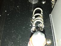
The resistor number R02 on the power supply section shorted,
I am planning to replace it ,but am afraid it would escalate to another problem, this all started when i replaced the trimpot for the dc offset of the left channel, since the trim pot was not able to trim the voltage.
I did this is to try to fix my actual or initial problem ,which was no signal outptut on the left channel.
Hope someone out there could give me a heads up on what to lookout for before i replace the resistor.
Attachments
I'd start with the basics like voltage measurements first. Do you have a variac or other means to slowly bring up the voltage?
Remove all the tubes and then set the input voltage to say 10%. See if you have ac going into the bridge rectifiers. If you removed R02 you could set your meter to measure current and see what the current reads while slowly increasing the voltage. You'll see the filter caps charging and then leveling off to nearly nothing.
If everything looks good then try replacing the resistor and watch the voltages as you slowly increase.
If everything looks good then try replacing the resistor and watch the voltages as you slowly increase.
Great, thanks mucho for this.
Another question, the schematics i uploaded seems wrong, the offset trimpot(R08) must be 200ohms as opposed to the schematic's that says 50k.
Another question, the schematics i uploaded seems wrong, the offset trimpot(R08) must be 200ohms as opposed to the schematic's that says 50k.
Hi Astouffer, you were right to check on the bridge rectifiers, found a bunch of bad diodes.
Our local electrical suppliers don't have this type of rectifiers, i want to maintain its look.
can somebody suggest the brand or type of this diode?
Our local electrical suppliers don't have this type of rectifiers, i want to maintain its look.
can somebody suggest the brand or type of this diode?
Try to get BYW96E diodes.
Regards, Gerrit
thanks Gerrit, found some fleabay
Try to get BYW96E diodes.
Regards, Gerrit
thanks Gerrit, found some fleabay
still need help
Hi still need help on my gm20,
I just checked all the diodes again,
The diodes are all fine,
if not , the power transformer will overheat.
With the variac at 50V AC
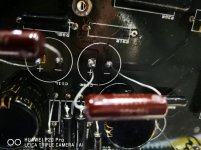
Resistor R01 is overheating and reaching 3 watts already.
Along with r31 on the same channel is also heating up.
Can not find the culprit up till now.
Hi still need help on my gm20,
I just checked all the diodes again,
The diodes are all fine,
if not , the power transformer will overheat.
With the variac at 50V AC
Resistor R01 is overheating and reaching 3 watts already.
Along with r31 on the same channel is also heating up.
Can not find the culprit up till now.
Have you checked the capacitors after the diodes? Does R31 overheat without the tubes for that channel?
Regards, Gerrit
Regards, Gerrit
Have you checked the capacitors after the diodes? Does R31 overheat without the tubes for that channel?
Regards, Gerrit
yes , checked fine the bridge diode b01 and b02.
yes r31 is heating up also w/o tubes, but only at full power (230v ac or 110v ac).
r1 measures 14.5v dc , r2 measures 8.75v dc.
Please help, i am facing a stone wall !!!
R31 is shorting, C1 is burning.
C1 and C2 shows that they are in series aiding, but measuring C1, but when measured there is series opposing polarity or there is negative 300vdc reading on C1. on C2 280vdc.
R31 is shorting, C1 is burning.
C1 and C2 shows that they are in series aiding, but measuring C1, but when measured there is series opposing polarity or there is negative 300vdc reading on C1. on C2 280vdc.
Please help, i am facing a stone wall !!!
R31 is shorting, C1 is burning.
C1 and C2 shows that they are in series aiding, but measuring C1, but when measured there is series opposing polarity or there is negative 300vdc reading on C1. on C2 280vdc.
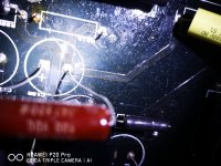
Sorry , i mean C13 and C11 , not C1 and C2. C13 measures negative 300vdc and C11 positive 280 vDC , they are in series.
found the culprit, there was a short on the board between the two pins of C13 slot,
the carbon trace was caused by the same leaky 150uf cap, that gradually shorted itself.
no wonder each new cap starts heating and burns up r31, even without all the tubes and all the resistor loads disengaged.
thanks again for the suggestions, using the variac to test saved my amp.
the carbon trace was caused by the same leaky 150uf cap, that gradually shorted itself.
no wonder each new cap starts heating and burns up r31, even without all the tubes and all the resistor loads disengaged.
thanks again for the suggestions, using the variac to test saved my amp.
Attachments
- Home
- Amplifiers
- Tubes / Valves
- graaf gm20 shorting resistor