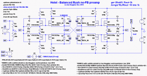
Anyone seen Rush pairs used like this?
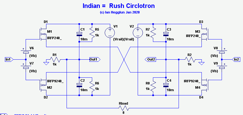
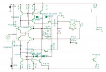
It is balanced in and balance out. Could be unbalanced in (by grounding one input) or a phase splitter (one input grounded and two output each wrt common).
Unlike the normal Circlotron this one has voltage gain, effectively common source.
Like a normal Circlotron it is symmetrical so even harmonics cancel. The p-channel and n-channel differences cancel -- you don't need to use well matched complements to get low 2nd harmonic distortion.
It can be biased for Class-A or Class-AB. In Class-A it approximates square-laws so the bias current can be about half that of standard push-pull Class-A with smaller heatsinks and transformers and caps. It can be used as a no feedback amplifier with current drive output.
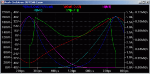
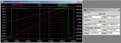
In Class-AB there is an optimum bias for minimum crossover distortion, it is quite high bias (since there are no source resistors) giving low distortion over the first watt. It can be used as a no feedback amplifier with current drive output. The attached plot is with 300mA bias and 25V supplies giving about 0.01% THD at 1W/8R.
The bias current for Class-A or Class-AB needs to be stabilized with Vbe 2 multipliers (or thermistors) to prevent thermal runaway.
Best wishes to all here for 2020 and beyond.
Cheers,
It is balanced in and balance out. Could be unbalanced in (by grounding one input) or a phase splitter (one input grounded and two output each wrt common).
Unlike the normal Circlotron this one has voltage gain, effectively common source.
Like a normal Circlotron it is symmetrical so even harmonics cancel. The p-channel and n-channel differences cancel -- you don't need to use well matched complements to get low 2nd harmonic distortion.
It can be biased for Class-A or Class-AB. In Class-A it approximates square-laws so the bias current can be about half that of standard push-pull Class-A with smaller heatsinks and transformers and caps. It can be used as a no feedback amplifier with current drive output.
In Class-AB there is an optimum bias for minimum crossover distortion, it is quite high bias (since there are no source resistors) giving low distortion over the first watt. It can be used as a no feedback amplifier with current drive output. The attached plot is with 300mA bias and 25V supplies giving about 0.01% THD at 1W/8R.
The bias current for Class-A or Class-AB needs to be stabilized with Vbe 2 multipliers (or thermistors) to prevent thermal runaway.
Best wishes to all here for 2020 and beyond.
Cheers,
Attachments
Last edited:
Here's a variant with non-floating supplies for preamps or headphone amps.
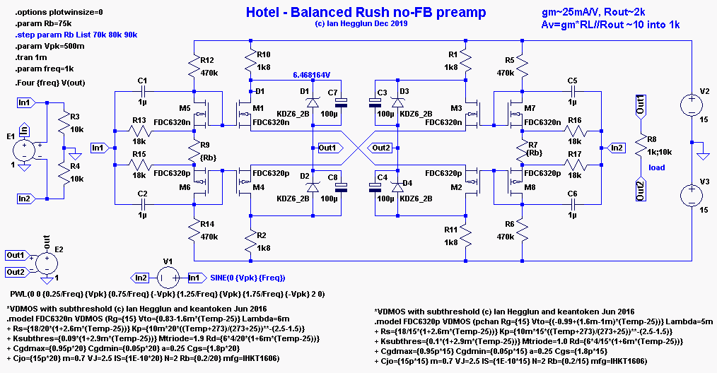
It uses zeners and caps for internal floating voltages. Here 6V zeners and +/-15 supplies gives 10Vpk output. See attached plot. The first 4V is low distortion (~0.01%) operating in the Square-law Class-A region and that's with a voltage gain of 10 and no feedback.
It uses zeners and caps for internal floating voltages. Here 6V zeners and +/-15 supplies gives 10Vpk output. See attached plot. The first 4V is low distortion (~0.01%) operating in the Square-law Class-A region and that's with a voltage gain of 10 and no feedback.
Attachments
I've been working with crossed Rush pair transconductance stages for a year or so now, closer to the first schematic than the second - neat idea for that second input structure, Ian. But because I'm looking for voltage gain not power gain, I'm using JFets. Got a working power amp front-end with feedback as well as nice open-loop MM phono pre up and running, haven't built up MC because I don't have an MC cartridge.
Hi AndriyOL,Very interesting design.
Can input devices be substituted with bjts?
Cheers.
Sure. Here's the preamp with BJT's and rebiased for 10Vpk swing. It gives about 6 times the gain of the earlier MOSFET for the same bias current and output swing and same load. The BJT version is less linear than the MOSFET version (see plot). The low THD range at say 1V swing it is 0.06%.
A BJT Diamond version is more linear (see next post).
Cheers,
Attachments
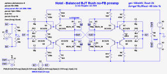

Here's the diamond BJT version of the preamp

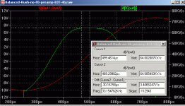
The rising gain in this Diamond is flattened by starving the Diamond input transistors (see attached plot). It gives 0.004% THD for 2Vpk swing.
Above 2V output the gain is rolled-off giving some nice soft clipping. This also reduces the swing into 1k load so the collector resistors are increased and then the load is increased to 2k to get the full 10V output swing for +/-15V rails.
Cheers,
Attachments

Hi rco3,I've been working with crossed Rush pair transconductance stages for a year or so now, closer to the first schematic than the second - neat idea for that second input structure, Ian. But because I'm looking for voltage gain not power gain, I'm using JFets. Got a working power amp front-end with feedback as well as nice open-loop MM phono pre up and running, haven't built up MC because I don't have an MC cartridge.
Nice to hear from you. Did you come up with this idea or is it already used or published somewhere?
Do you use any degeneration in the sources? Or any overall feedback?
Are you using PV IC's for the floating supplies. Or maybe solar cells?
That's only if you are willing to give away your ideas. Otherwise please PM me.
Cheers,
I am also developing a push-pull Rush VFA for 150/300w amp. I dedicated all the trans Conductance gain to input stage running it at 10ma. To have the maximum trans Conductance I kept non degenerated emitters but I added a DC current feedback to adjust the bias 10ma. My be this same technique can also be applied to your circuits.
What is PV ICs?
What is PV ICs?
Attachments
Last edited:
Hi, Ian.
I'm hesitant to claim primacy in any audio circuit, or electronic circuit in general for that matter. I'm no Scott Wurcer, Erno Borbely, nor Ian Hegglun - but no, I'd never seen that particular combination before really late one night about a year ago or so, and then again now. Obviously some differences like floating power supplies, output mode, etc., but I'd really like to talk more about it, probably PM as you suggested.
I use (so far) a configuration that ends up with + and - inputs and a single high impedance current-source output - classic textbook transconductor. For the last several months I've been listening to a couple of prototypes. One is an MM RIAA preamp: balanced-input (although RCAs so - side grounded), zero-feedback, with no source degeneration. I've got a working power amp design with a similar gain stage but closed-loop Av=10, wrapping the power stage (MoFo-like) in the FB loop. The working prototype has HLMP-6000 red LEDs in the source circuits, but that was a hack as part of troubleshooting a problem that turned out to be an assembly issue. I left them in to save some heat on the JFets, dynamic impedance is really low so not really a lot of degeneration at signal frequencies. Again, worthy of some discussion.
So far I've only worked this with JFets because I think this core idea is really optimal for depletion devices, or at least easiest, and that's JFets or DefiSit-type depletion/enhancement combinations. I'll need to peruse and consider your BJT implementation, thanks much for the inspiration.
I am also developing a push-pull Rush VFA for 150/300w amp. I dedicated all the trans Conductance gain to input stage running it at 10ma. To have the maximum trans Conductance I kept non degenerated emitters but I added a DC current feedback to adjust the bias 10ma. My be this same technique can also be applied to your circuits.
What is PV ICs?
Hi kokoriantz,
Nice to know the criss-crossed Rush diamond thingi is known. Did you see it used before anywhere? Has it got a name?
For your circuit is there some temperature compensation in there somewhere? How stable is the current and hence gain with temperature?
A "PV IC" like used for speaker protection MOSFET SSR's. EG VO1263 is a dual photovoltaic DC-DC converter 13V out into 1Meg with 10mA input at 1.5V.
A bit expensive if you want floating supplies at say 50uA, but. OK for a flea power floating 15uA dual supply.
Hi rco3,Hi, Ian. I'm hesitant to claim primacy in any audio circuit, or electronic circuit in general for that matter. I'm no Scott Wurcer, Erno Borbely, nor Ian Hegglun - but no, I'd never seen that particular combination before really late one night about a year ago or so, and then again now. Obviously some differences like floating power supplies, output mode, etc., but I'd really like to talk more about it, probably PM as you suggested..
Unless someone drops in here with an earlier date for using this "crossed Rush" combo we will have to give it a name that you choose, else the "Crossed Rush Combo" by default, or "The RCO3" or any other suggestion that is popular.
I hope to PM you soon.
Cheers,
Hi AndriyOL,What's an upper range of response Ian for mosfet and diamond bjt versions?
With 1k source resistance the BJT diamond and MOSFET versions both roll-off -3dB at 800kHz.
But the gain BW products are 50MHz and 8MHz respectively.
And the 180 degree frequencies are 1GHz and 130MHz respectively.
So the BJT diamond version is better than the MOSFET version by a mile.
Cheers,
What about low input resistance for current output dacs? I don't remember exactly how much low it should be.
Hi AndriyOL,
For current output DACs place a resistor across the preamp stage balanced inputs to obtain the datasheet value. If your DAC needs termination on each output to common then use two resistors. So the preamp itself does not necessarily need to have a low resistance to match the DAC as long as these extra resistors are added. The signal to noise ratio may be degraded this way but if this step is not the dominant noise component then it is OK.
But if the signal to noise ratio needs to be kept as low as possible at this point then use just the right amount of shunt voltage feedback around the preamp to reduce the preamp input resistance to load the DAC.
That's my thoughts. But I don't have experience using DACs. Anyone who knows?.
Hi Ian,
Nice iDeas!
Some years ago I played with the “Rush-cascode” but I never got the thing stable!
At That time I think it was Hugh Dean(AKSA) who brought this up.
After a while I left this one also in the closet and builded a Pass-design.
Maybe it’s time to pick it up again.
Thanx for sharing!
Ed
Nice iDeas!
Some years ago I played with the “Rush-cascode” but I never got the thing stable!
At That time I think it was Hugh Dean(AKSA) who brought this up.
After a while I left this one also in the closet and builded a Pass-design.
Maybe it’s time to pick it up again.
Thanx for sharing!
Ed
You won't find them in the wild, Hayk. I designed a few amps with the Rush 12 years ago, and it took some time to get it right, so I decided to keep it to myself. The Rush has many advantages; linear, quiet, fast, and dominant H2.
Look at Diego's mosfet circuit here.
https://www.diyaudio.com/forums/sol...fier-trilogy-plh-jlh-amps-58.html#post5941769
He did a good one and it worked well as a HPA.
Hugh
Look at Diego's mosfet circuit here.
https://www.diyaudio.com/forums/sol...fier-trilogy-plh-jlh-amps-58.html#post5941769
He did a good one and it worked well as a HPA.
Hugh
Last edited:
Member
Joined 2009
Paid Member
Thank you for confirming that my Rushed F5 not any similar of yours.
Hayk
he may have looked at something similar and discarded it along the way... ‘theres nothing new under the sun’ or so I keep reading
I simulated a symmetrical Rush some years back, but I lost interest in symmetrical designs for front end although my TGM7, which is symmetrical but not a Rush, is not too shoddy
Hugh gave you a hint already but you missed it because you are very set on your current design... he said “dominant H2”, something that lends a character that you don’t usually get with a well-matched symmetrical front end. Afterall, if we seek only lowest possible distortion we fail to understand the art of sound and merely repeat the goals of many.
Last edited:
- Home
- Amplifiers
- Solid State
- Has anyone seen Rush pairs used this way?