My KA-5002 is not working. I may have narrowed it down to the amp board when I experienced no issues using an amp board from a working donor. There is a short somewhere I cannot narrow it down further. Test points are good until the protection circuit and B-.
Drivers are new KSA1220AY/KSC2690AY pair. Diff inputs are also new, and I can center those with Vr1,2 fine according to service manual.
B- drops to -24v on a 40w dim bulb. If I pull the output transistors it gets proper -35v on dim bulb, bulb is dark, relay clicks. With outputs in, the bulb is really dim, then brightens up a little after 2 seconds, no relay engagement.
I checked resistance of the output emitter resistors they all are good. I did diode test on the output transistors twice, check out good. Unit works with donor board, relay clicks in fine.
I did find and replace a bad De6 flyback diode.
When powering on with dim bulb, Qe18 collector briefly surges to 30V, then drops to 3v. Qe17 emitter reads 3v on dim bulb.
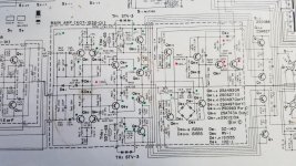
I need help from the pros! I would appreciate your investigative skills. I put red dots on test points that read bad. Pins 6 and 14 go to relay, it got cut off.
Kind regards.

Drivers are new KSA1220AY/KSC2690AY pair. Diff inputs are also new, and I can center those with Vr1,2 fine according to service manual.
B- drops to -24v on a 40w dim bulb. If I pull the output transistors it gets proper -35v on dim bulb, bulb is dark, relay clicks. With outputs in, the bulb is really dim, then brightens up a little after 2 seconds, no relay engagement.
I checked resistance of the output emitter resistors they all are good. I did diode test on the output transistors twice, check out good. Unit works with donor board, relay clicks in fine.
I did find and replace a bad De6 flyback diode.
When powering on with dim bulb, Qe18 collector briefly surges to 30V, then drops to 3v. Qe17 emitter reads 3v on dim bulb.
I need help from the pros! I would appreciate your investigative skills. I put red dots on test points that read bad. Pins 6 and 14 go to relay, it got cut off.
Kind regards.
Attachments
Disconnect the collectors of the output transistors and the load and repeat the voltage measurements.
Much thanks. With Output collectors disconnected, relay engages, bulb is dark. I will check voltages now.
I 'm not following you, are you referring to bad output or driver?Possible breakdown of powerful BJT...
All failed test points still measure bad
B- = -24v
Qe18 base = 35v
De6 anode = 18v
Qe17 E = 3.6v, C = 36v
Qr18 C = 35v then drops to 4v
I noticed all 4 drivers are hot, 140F
B- = -24v
Qe18 base = 35v
De6 anode = 18v
Qe17 E = 3.6v, C = 36v
Qr18 C = 35v then drops to 4v
I noticed all 4 drivers are hot, 140F
For a long time do not keep on - the emergency mode. They can bask without powerful ones.
All transistors are interconnected.
All transistors are interconnected.
Do these figures look out of ordinary?
Qe13 E= -10mV C = 39V, B = -10mV
Qe14 E = -25mV, C= 35V, B = -17mV
Qe15 E= -6mV, C= 36V, B= -8mV
Qe16 E= 39V, C= -200mV, B=35V
Qe13 E= -10mV C = 39V, B = -10mV
Qe14 E = -25mV, C= 35V, B = -17mV
Qe15 E= -6mV, C= 36V, B= -8mV
Qe16 E= 39V, C= -200mV, B=35V
I took same readings from working unit
Qe13 E= 78mV C = 48V, B = -62mV
Qe14 E = 69mV, C= 48V, B = 2mV
Qe15 E= 30mV, C= 48V, B= 20mV
Qe16 E= 48V, C= 5mV, B=48V
Readings from not working unit
Qe13 E= -10mV C = 39V, B = -10mV
Qe14 E = -25mV, C= 35V, B = -17mV
Qe15 E= -6mV, C= 36V, B= -8mV
Qe16 E= 39V, C= -200mV, B=35V
There is approx. 9v-12v discrepancy for all the above off readings, 10v discrepancy for B-
One anomaly I found on both amp boards, 100uf is installed instead of 220uf for Ce18 position as shown on schematic.
Since De6 was previously shorted, I pulled and tested Ce17 33uf, which tested good. I replaced it anyways. Schematic shows 47uf in that position although 33uf is also in the working board.😕
Although some voltages are low, it is safe to declare Qe13-18 are not the cause?
Could semiconductor short or shorted metal film be causing voltage drop?
Could semiconductor short or shorted metal film be causing voltage drop?
Boy this one is getting the best of me. I reattached the collector wires to outputs. Found I made bad choice for De1 DZ-140 sub had in 1n4148, replaced with 1N5244B.
Although they tested fine I replaced the last two semis i hadnt swapped out Qe7,8 bias transistors with ZTX696B. Unit came out of protection, B+ still sagging like an old ladies tits by 12v, bulb lightly dimmed. Turned on/off few times, wont come out of protection again. Turned bias pots all the way to nearly 0. Came out of protection again.
Pondering tracing a signal to see where it becomes a problem but unsure if the -12V sag will defeat that effort.
Transistors 13-16 form a protection circuit. 13-14 amplify the voltage from the emitter resistors of the output transistors 1-4.
Amplifier 1-12 + (1-4). Check voltages.
Amplifier 1-12 + (1-4). Check voltages.
Q1 E=.67V C=-22V B=.56V
Q2 E=.65V C=-21V B=.53V
Q3 E=.77V C=-23V B=.13V
Q4 E=.76V C=-23V B=.13V
Q5,Q6 DONT EXIST
Q7 E=-21V C=-.9V B=-22V
Q8 E=-23V C=-1.3V B=-23V
Q9 E=.35V C=24V B=.9V
Q10 E=.74V C=23.9V B=1.3V
Q11 E=-.38V C=-23V B=-9V
Q12 E=-1.3V C=-23V B=-1.3
Kind regards.
Q2 E=.65V C=-21V B=.53V
Q3 E=.77V C=-23V B=.13V
Q4 E=.76V C=-23V B=.13V
Q5,Q6 DONT EXIST
Q7 E=-21V C=-.9V B=-22V
Q8 E=-23V C=-1.3V B=-23V
Q9 E=.35V C=24V B=.9V
Q10 E=.74V C=23.9V B=1.3V
Q11 E=-.38V C=-23V B=-9V
Q12 E=-1.3V C=-23V B=-1.3
Kind regards.
TR1 E=85mV C=23V B=.74V
TR3 E=115mV C=-23V B=-.76
TR2 E=-15mV C=23V B= .32V
TR4 E=.4mV C= .4mV B=.4mV
correction on Q11 B=-.9v
Bad Tr2,Tr4?
TR3 E=115mV C=-23V B=-.76
TR2 E=-15mV C=23V B= .32V
TR4 E=.4mV C= .4mV B=.4mV
correction on Q11 B=-.9v
Bad Tr2,Tr4?
Q11 B-E = 22V
Q12 B-E = -22V
Q7 B-E = .56V
Q8 B-E = .56V
STV3 R= 1.56V L=1.55V ON DIODE TEST (R LOOKS A LITTLE BURNT)
SDT65 R= 800OHM L=800OHM
6 POINT DIODE TEST PASS ON TR2,TR4 DROP = .55V
Q12 B-E = -22V
Q7 B-E = .56V
Q8 B-E = .56V
STV3 R= 1.56V L=1.55V ON DIODE TEST (R LOOKS A LITTLE BURNT)
SDT65 R= 800OHM L=800OHM
6 POINT DIODE TEST PASS ON TR2,TR4 DROP = .55V
You have a classic Lin amplifier: LTP Q1 (2), 3 (4) + V ac Q7 (8) + EF1 driver Q9 (10), 11, (12) + EF2 powerful Q1 (2), 3 (4)
Appreciate the assistance. I remeasured Tr4 today and got a different reading
E=.4mV C=-23v B=-.350mV
When amp is turned on, before relay engage, E=40mV... then drops to .4mV after engaged.
Tr4 does not seem to be opening although it passed a diode test. I may experiment with On Semi replacements MJ21193/MJ21194 for Tr2,Tr4 unless advised otherwise.
E=.4mV C=-23v B=-.350mV
When amp is turned on, before relay engage, E=40mV... then drops to .4mV after engaged.
Tr4 does not seem to be opening although it passed a diode test. I may experiment with On Semi replacements MJ21193/MJ21194 for Tr2,Tr4 unless advised otherwise.
TR1 E=85mV C=23V B=.74V
TR3 E=115mV C=-23V B=-.76
TR2 E=-15mV C=23V B= .32V
TR4 E=.4mV C= .4mV B=.4mV
correction on Q11 B=-.9v
Bad Tr2,Tr4?
Replaced Tr2,Tr2 and she finally came out of protection and dim bulb was dark.
Now I read 87mV on both of those emitters instead of 4-15mV
Looks as though the 6 point diode test results are not 100% definite
 .
.Only took 6 years to sort this one out! 😀
- Home
- Amplifiers
- Solid State
- Need help on Kenwood repair