WICH IS THE OUPUT POWER FOR ONE SE 6550 TRIODE AMP ?
THE +B is 385VCC , CURRENT 85mA AND PLATE LOAD 4.2K.
Thanks you.
THE +B is 385VCC , CURRENT 85mA AND PLATE LOAD 4.2K.
Thanks you.
Well . . .
Was the question for a Triode (wired) amp?
Much much less than 13 Watts.
Or, was it for a Tetrode (Beam Power Tetrode) amp?
13 Watts.
Plate swinging down to 50V.
385V - 50V = 335V peak swing
((Peak Volts)Squared)/(2 x 4200 Ohms) = 13W rms
Of course as the tube nears cut off, it can swing up by lots more than 335V, but that is all 2nd harmonic energy.
Well . . .
Was the question for a Triode (wired) amp?
Much much less than 13 Watts.
Or, was it for a Tetrode (Beam Power Tetrode) amp?
13 Watts.
Plate swinging down to 50V.
385V - 50V = 335V peak swing
((Peak Volts)Squared)/(2 x 4200 Ohms) = 13W rms
Of course as the tube nears cut off, it can swing up by lots more than 335V, but that is all 2nd harmonic energy.
6a3sUMMER , thanks.
The question are because I always had 300B amplifiers with 7 or 8 W/ Ch, and 95dB or more speakers.
Today I have a 6550 SE triode amp and a 90dB Bower Wilkins 602.
Together they work very well, so I think it can have some watts more (maybe 10w ) with the 6550 as a triode.
Thanks,
Ok, here it is.
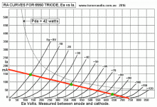
Graphic calculation for a datasheet perfect 6550
* idle conditions: 385V - 85mA - Load=4200 ohm
* I draw idle point (center green dot) and a 4200 ohm load line crossing it.
Let´s see how far can we swing either way along it.
* Being a Class A1 amplifier (no grid current allowed), maximum grid voltage allowed is 0V
Which shows me saturation voltage is 132V , passing 142mA current; left green dot.
That defines peak signal voltage and current swing.
* Then opposite peak voltage and current *might* be higher because we have not reached "a wall" but as 6A3Summer says, that will be an assymmetrical extra peak, "second harmonic" power, maybe useful and even desirable in a Guitar amp but we are talking Hi Fi here, so we stop as soon as we reach clipping or heavy curve bending, either way..
* We "should" fine tune the design by analyzing inherent assymmetry since positive and negative drive voltage swing to reach those points is not the same, and accounts for typical few % "soft" distortion of Tubes but that´s beyond today´s task 😉
* So the opposite peak will be 638V, at which point it will be passing 26 mA , shown as the right green dot.
* Peak Power: Peak Voltage swing * Peak Current swing= 253V*59mA=14.92W so 7.5W RMS.
That with a datasheet perfect tube, and zero transformer loss; actual power with a good tube and OT will be around 90% of that.
Attachments
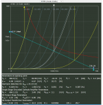
See the attached graph of the KT88 in SE triode mode. The '88 and the 6550 are quite similar. Power output at the plate is 6 watts. Power output (at the transformer secondary) should be somewhere around 5W - 5.5W accounting for transformer loses.
I would be careful about your B+ at 385V requirement. B+ is not the plate to cathode voltage that the tube sees. You need to account for both the voltage drop at the OPT and the drop at the cathode resistor if the circuit is cathode biased. In this specific example of the KT-88, there would be a 41V drop at the cathode resistor and another 15V - 20V drop at the transformer primary. At your stated B+ voltage the tube would see around 325 Vp-k
FYI, at 325V through the tube at the same 85mA OP the output is just under 4W
Attachments
Last edited:
musical noise,
The request is for an SE amplifier, not push pull.
You can not stand 6 Watts in a plate, and get 4 watts out, even before the transformer losses.
If you want 6 Watts plate dissipation, and want 6 Watts out, build a switching Class D amplifier.
The biggest difference between the 6550 and the KT88 is:
Fixed Bias, g1, maximum resistance:
6550 50k; KT88 100k.
Thermal Run Away is the issue.
Last edited:
I used the wrong word by writing plate dissipation where I should have said "power at the plate". I corrected the wording but the rest still stands. Plate dissipation if we take the entire 385V plate to cathode voltage, is actually 385 x 0.085=33W.
At a 6W output that gives a plate efficiency (and I'm using the term loosely) at around 18% which is inline with most IDH power tubes when run in SE triode mode.
At a 6W output that gives a plate efficiency (and I'm using the term loosely) at around 18% which is inline with most IDH power tubes when run in SE triode mode.
Last edited:
I mis-read your text.
But at least a newbe will learn something about the concept of single ended power dissipation versus power out.
Yes, 18% sounds very reasonable.
But at least a newbe will learn something about the concept of single ended power dissipation versus power out.
Yes, 18% sounds very reasonable.
The question came to me because for years I had an amplifier with 300B with 7W, with some 96dB speakers. Now I have a 6550 trio mode, and 89dB Wilkins Bowers and they work very well. So I thought that it could have the same or more than the 300B
- Home
- Amplifiers
- Tubes / Valves
- Which is the output power for one SE 6550 triode amp