Can I suggest 'divide and conquer' first. All of a sudden there is a whole cake in the mixing bowl.
Why is L6 in the amp in that location?
Are you able to go back to just presenting a spectrum plot where only the output stage is in the mix, and to step through making a change to the bias supply to get some confidence that the bias is not the main contributor to your hum.
Apart from bias related hum, a step change to B+ related hum, and to screen related hum would seem to me to be the first steps to take. If there is still significant hum being measured, then the focus probably turns to grounding, and to magnetic interaction between PT and OT.
...but I like cake 😀.Can I suggest 'divide and conquer' first. All of a sudden there is a whole cake in the mixing bowl.
The original doesn't have a choke, the hum/buzz/noise was too high, therefore I took a chocke from a chinese 845 SE (have nothing else).Why is L6 in the amp in that location?
According to the majority of what I read, this position is as good as the one of the 33R (R23). Some claim the R23 position is better as there is capacitive coupling through the secondary. Others suggest to split the R23 in two, and use one half at R23 and one at L6 position.
The choke has 23R, it was MUCH easier (and safer) to realise the L6 position and it seems to work 🙂, but if you suggest otherwise, just tell me what to do.
Sorry, I should have done that already.Are you able to go back to just presenting a spectrum plot where only the output stage is in the mix, and to step through making a change to the bias supply to get some confidence that the bias is not the main contributor to your hum.
The amp has right channel without 120k / 2M2 local feedback and the grid coupling caps removed, standard bias, no KT88 in the left channel.
Taking into account that you suggested the mod, the sim confirmed the mod and comparing the measurements to the old ones, I didn't rebuild the bias (takes me about an hour for everything). If you think it is necessary I will do it, please advise, otherwise I just repeat - thank you !
The two last measurements are the old ones for comparison.
Oscilloscope setting 2ms, 5mV, 1:10 probe I get about +/- 150 mV steps on the bias worst case.Apart from bias related hum, a step change to B+ related hum, and to screen related hum would seem to me to be the first steps to take.
I can confirm the bias is 'jumping' opposite to the HV, if the HV increases, the bias decreases, just as if one would vary the mains voltage. The mains voltage is slowly fluctuating about 10 Vrms during the day(s). The short term variations seem to be about 100 mVrms, which would be about 50 mV for the bias, the osci is faster than the DMM (the DMM steps appear to be slower).
I am sorry, I don't know how or what exactly you want me to measure or modify, please advise.
While measuring I slided the pot on and off the PT which didn't show even a tiny change in the spectrum. The pot is made from 3mm aluminium.If there is still significant hum being measured, then the focus probably turns to grounding, and to magnetic interaction between PT and OT.
Orientation is OPT-PT-OPT (90°) and the axis of the windings of the PT is pointing at the KT88s. Is there a number how big the distance usually has to be (the OPT and the PT pots have less than 1 cm spacing) ?
Attachments
-
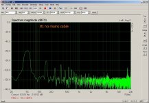 #01 no mains cable, right channel 8R.jpg178.7 KB · Views: 124
 -
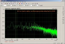 #02 no mains cable, oscilloscope attached, right channel 8R.jpg191.2 KB · Views: 133
 -
 #03 mains cable plugged in, amp off, right channel 8R.jpg182.1 KB · Views: 127
 -
 #04 mains cable plugged in, osci attached, amp off, right channel 8R.jpg187.1 KB · Views: 127
 -
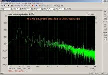 #05 mains cable plugged in, osci attached, amp on, tubes cold, right channel 8R.jpg187.2 KB · Views: 125
 -
 #06 mains cable plugged in, osci attached, amp on, tubes hot, right channel 8R.jpg183.8 KB · Views: 43
 -
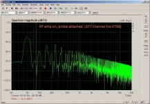 #07 mains cable plugged in, osci attached, amp on, no KT88, left channel 8R.jpg193.8 KB · Views: 48
 -
 #6_probe right.jpg192.4 KB · Views: 43
 -
 #5_probe left.jpg189.2 KB · Views: 35
Sometimes Hum and Noise is caused by Ground Loops from, you guessed it:
The amplifier under test, and the measurement equipment (and computer if present).
Mains fundamental, Mains harmonics, switching power supplies, etc.
Even your CFC lamps, LED lamps, etc.
All these have have Conducted EMI and Radiated EMI.
Devices that meet all the EMI regulations, can still interfere with one another.
My former co-worker and friend has all Linear LED lighting in his room where testing is done to the double and single digit uV levels.
Many think that a scope probe ground clip will eliminate hum and noise when correctly cdonnected.
Not always true. Any AC or RF current in the shield will cause a signal in the center conductor.
An example ground loop is from Amplifier, to probe, to scope/computer, to mains power of the scope/computer, to mains power of the Amplifier.
And no isolation transformer is perfect. It can still conduct high order mains power harmonics and switcher noise.
"Grounds Are Commonly Misunderstood" - Me
If you look for dirt under the rug, you will find it.
Last edited:
"The amp has right channel without 120k / 2M2 local feedback and the grid coupling caps removed, standard bias, no KT88 in the left channel."
Can you clarify which plot is the right channel speaker output for this configuration?
I could suggest that configuration would be a good 'base case', from which to do single step testing (ie. make only one change to a part of a section, and take a plot measurement and identify what if any change occurs to the plot).
Single step tests could include:
- doubling the final filter capacitance used for smoothing the bias supply.
- doubling the final filter capacitance used for the B+ supply to output transformer.
- making a temporary common RC filtered screen supply (ie disconnect the UL connections and take to the filtered screen voltage.
The above tests just aim to indicate if any one supply is introducing significant hum.
If there was no change to the plots, then the focus would move on to other possible causes.
I would suggest removing the L6 choke for the moment.
When temporarily connecting any additional filter capacitance, make sure the capacitor terminals connect as directly as possible to:
- the OT B+ lead
- the end of the 10 ohm cathode sense resistors
- the top of the bias pots
This is in case you have some additional common wire paths with your existing wiring that may be introducing hum.
"While measuring I slided the pot on and off the PT which didn't show even a tiny change in the spectrum. The pot is made from 3mm aluminium."
This is a valid form of faultfinding, although using aluminium would only modify capacitive interactions. A relatively thick walled steel 'pot' would be needed to influence magnetic coupling, and you may find it easier to use a thick flat sheet of steel between the PT and the right channel OPT. Sometimes it is just better to temporarily remove an OPT, or PT, some distance away from the chassis on carefully installed link wiring. Or another option is to temporarily unbolt a transformer and rotate it (if practical to do it safely).
Last edited:
Sorry, I was lazy with the description. The first 6 plots (#1-#6 in the filenames) are right channel plots, #7 has left in the description as the two old plots."The amp has right channel without 120k / 2M2 local feedback and the grid coupling caps removed, standard bias, no KT88 in the left channel."
Can you clarify which plot is the right channel speaker output for this configuration?
Sometimes Hum and Noise is caused by Ground Loops from, you guessed it:
The amplifier under test, and the measurement equipment (and computer if present).
Mains fundamental, Mains harmonics, switching power supplies, etc.
Even your CFC lamps, LED lamps, etc.
I for sure have to switch off the lights and I have my doubts about the measurements, therefore I tried to check ARTA measurements with the DMM and the headphones.
"Grounds Are Commonly Misunderstood" - Me
If you look for dirt under the rug, you will find it.
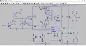
I am still far away from your sub 100 µV mark. Do you see any problems in the attached schematic ?
Attachments
I could suggest that configuration would be a good 'base case', from which to do single step testing (ie. make only one change to a part of a section, and take a plot measurement and identify what if any change occurs to the plot).
Single step tests could include:
- doubling the final filter capacitance used for smoothing the bias supply.
I did some more measurements. The amp as in the previous post, but grid coupling caps disconnected at right channel and 1k||120k and 2M2 open to remove local feedback('Supertriode'). The additional extra 100µF filter capacitance was added in the best possible position.
I am a little bit concerned to kill the tubes by switching them on/off quite often for the measurements. Would it be a good idea to buy a dimmer to ramp up the voltage during 30(?) seconds and than short the dimmer ?
Will post additional B+ filtering tomorrow.
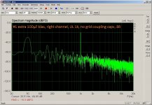
First 5 plots are done with the switch in UL mode, last one switched to triode mode. Plot #2 and #5 have the extra 100µF for the bias (C16 doubled). The rest is wether with/without choke or GND (0 V reference) connected directly to PE or through the diode bridge.
The choke and the diode bridge make audible improvements.
Attachments
-
 #1 right channel, UL 1k, no grid coupling caps, 8R_SPA.jpg191.3 KB · Views: 59
 -
 #2 extra 100µF bias, right channel, UL 1k, no grid coupling caps, 8R_SPA.jpg189.3 KB · Views: 47
 -
 #3 same #1, but no choke, right channel, UL 1k, no grid coupling caps, 8R_SPA.jpg196.6 KB · Views: 37
 -
 #4 same #1, but no choke, diode bridge to PE, right channel, UL 1k, no grid coupling caps, 8R_SP.jpg200.9 KB · Views: 36
 -
 #5 same #2, extra 100µF bias, but no choke, diode bridge to PE, right channel, UL 1k, no grid co.jpg205.2 KB · Views: 47
 -
 #6 same #4 but Triode mode, no choke, diode bridge to PE, right channel, Triode mode 1k, no grid.jpg203 KB · Views: 47
alojoe2,
I have to say that with all the gain in your amplifier, you might never get near to the 100uV level.
But we may be able to do some improvements.
Ground Loops; magnetic spray from power transformer and/or choke, to the output transformer; AC heater to cathode leakage of an individual tube; and other hum and noise sources are not all easily detected by looking at a schematic.
(but I love starting with a schematic, Thanks!).
Concerning magnetic spray being picked up by an output transformer, one of my amplifiers has a steel chassis (I wish it was aluminum).
Other than the obvious correct rotational orientation of the coils, there is not lots to be done about the high magnetic conductivity of a steel chassis.
So, I use a little Air . . . I put the Power Transformer, Choke, and Output Transformer all on 1/4 Inch round aluminum spacers. That way, the laminations do not sit directly on the steel chassis.
I have to admit, even with those aluminum spacers, I am getting 1mV of hum at the amplifier output.
Well, I notice 3 things about the schematic:
1. Both the SRPP input stage, and the Phase Invertor stage have what I call floating cathodes (they do not return the cathode to AC ground).
A bad tube (and there are many) that has lots of filament to cathode leakage, will pick up hum and noise from the filament winding
(I use spiral-wound-filament tubes in my input tubes; phase inverter tubes; and driver tubes).
The filament winding gets mains power fundamental and 3rd harmonic; and gets other noise from other mains power users; and gets some of the transient charge current noise of the B+ secondary and its rectifier and first filter cap, that is transferred to the filament winding.
2. What is the purpose of R26, 22 Ohms. It may be intended to reduce a ground loop, but instead it creates a ground loop.
Any wire (wire milli-Ohms, and wire inductance), and any 22 Ohm resistor are just the thing that any loop current will develop a voltage across.
Develop a voltage across the 22 Ohm resistor, and then potentially inject that voltage into the cathode of the bottom triode of the SRPP.
3. KT88 Fixed Bias:
</= 35 Watts, R g1 220k Maximum
>/= 35 Watts, R g1 100k Maximum
As drawn, with your 20k bias pot centered, each grid, g1 sees over 220k to ground.
That is a violation of safe operation.
And why are you worried about turning the tubes on and off?
What is the quiescent total plate and screen dissipation you are running in the KT88?
Unless they are overheated (above maximum ratings), they are meant to be turned on and off.
Last edited:
alujoe2,
You put L6 in the ground side of the B+ circuit;
and R23, 33 Ohms in the + of the B+ side.
Yes, L6 reduces (localizes) the B+ ground loop.
But then R23, 33 Ohms puts all of the remaining ripple current (and voltage) on the top of the second filter cap, and the second cap "floats".
Try putting L6 in the B+ lead between the + of the first filter cap, and the + of the second filter cap.
Then use separate wires in the ground path.
One wire from bridge negative (-) to first filter cap negative (-).
One wire from first filter cap negative (-) to the second filter cap negative (-).
One wire from the second filter cap negative(-) to the amplifier's central ground point.
Uh, you did use a choke that has a high enough voltage rating to not arc over when B+ goes to maximum voltage before the tubes warm up and draw current.
Otherwise, get a new choke before putting it in the + side of B+.
Also C1 is not very effective with R26, 22 Ohms in the circuit. Jumper across R26.
If you have bad problems with signal source ground loops, find a way to fix that outside of the amplifier circuits, not inside the amplifier circuits.
That is about all I can see at this time.
Good luck pushing the hum and noise down.
Last edited:
Post #42 plots indicate that bias related hum is not noticeable, but do indicate that B+ related hum is an issue (and that includes hum ingress from the screen via the UL connection to B+).
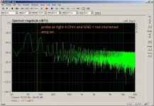
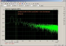
If the focus turns to the B+ supply, have you done two comparison plots for just the output stage (driver coupling caps disconnected) where the base case doesn't include the choke (to provide a simpler circuit - so just filter caps and the 33 ohm CRC filter), and a step case where you add a flying 470uF cap to the B+ OT lead and the 10 ohm cathode sense resistors? You may have done those plots, but best that you pick them out.
If there was a noticeable hum drop between those two setups, then can you confirm the original 470uF capacitor that feeds the output stage is connecting to the same physical circuit locations as your added test capacitor, and the 0V link back to the power supply bridge and first filter cap is not connected to any other 0V point.
Another issue is the 2nd channel also has such a 0V node at the output stage 10 ohm sense leads, and that is going to be a hum loop situation. So can you do a comparison test where the 2nd channel has its B+ connection in place, and then with no B+ connection (ie. no circuitry or filter caps get powered, and hence no 0V link currents from that channel).
Last edited:
Maybe better to put stainless steel on your wish list, as aluminum and copper both generate eddy currents. Is Aluminum Magnetic?alojoe2,
I have to say that with all the gain in your amplifier, you might never get near to the 100uV level.
But we may be able to do some improvements.
Ground Loops; magnetic spray from power transformer and/or choke, to the output transformer; AC heater to cathode leakage of an individual tube; and other hum and noise sources are not all easily detected by looking at a schematic.
(but I love starting with a schematic, Thanks!).
Concerning magnetic spray being picked up by an output transformer, one of my amplifiers has a steel chassis (I wish it was aluminum).
Other than the obvious correct rotational orientation of the coils, there is not lots to be done about the high magnetic conductivity of a steel chassis.
So, I use a little Air . . . I put the Power Transformer, Choke, and Output Transformer all on 1/4 Inch round aluminum spacers. That way, the laminations do not sit directly on the steel chassis.
I have to admit, even with those aluminum spacers, I am getting 1mV of hum at the amplifier output.
You are for sure correct, but I tried DC heating before and nothing changed. Seems to me that the elevated and bypassed AC heating was good enough before the improvement with the RC on the bias supply. Will keep an eye on that and try DC again.Well, I notice 3 things about the schematic:
1. Both the SRPP input stage, and the Phase Invertor stage have what I call floating cathodes (they do not return the cathode to AC ground).
A bad tube (and there are many) that has lots of filament to cathode leakage, will pick up hum and noise from the filament winding
(I use spiral-wound-filament tubes in my input tubes; phase inverter tubes; and driver tubes).
The filament winding gets mains power fundamental and 3rd harmonic; and gets other noise from other mains power users; and gets some of the transient charge current noise of the B+ secondary and its rectifier and first filter cap, that is transferred to the filament winding.
Yes, the wisdom is from the links in post #3.2. What is the purpose of R26, 22 Ohms. It may be intended to reduce a ground loop, but instead it creates a ground loop.
Any wire (wire milli-Ohms, and wire inductance), and any 22 Ohm resistor are just the thing that any loop current will develop a voltage across.
Develop a voltage across the 22 Ohm resistor, and then potentially inject that voltage into the cathode of the bottom triode of the SRPP.
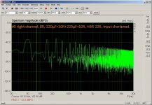
The HBR seems to work for problematic gear and might be a little bit worse on the bench in isolation.
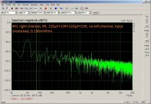
Soundcard outputs on amp inputs and amp 8R output attached to sound card:
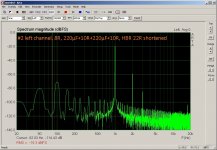
The DMM claims 1.029 mVrms for the shortened HBR 22R and 1.027 mVrms for the HBR 22R in place on the right channel with the disconnected grid coupling caps. On the left channel (ready for music) the values are around 396 mVrms and I can't detect a real difference (too much fluctuation).
Inputs shortened, soundcard not attached:
Right channel 0.186 mVrms and left channel about 1.1 mVrms (fluctuating). Shortening the HBRs seems to increase the readings in the left channel a little bit 1.2 mVrms(?) and it shows a lot more fluctuation. The right channel shows identical reading 0.186 mVrms (as it should be).
See attachments.
Fully agree, but I have the excuse it was just prototype testing with an amp being equipped with an overcurrent protection relay 🙂.3. KT88 Fixed Bias:
</= 35 Watts, R g1 220k Maximum
>/= 35 Watts, R g1 100k Maximum
As drawn, with your 20k bias pot centered, each grid, g1 sees over 220k to ground.
That is a violation of safe operation.
Anyhow it is history, as I ditched the 'Supertriode' circuit yesterday and switched back to Triode mode, no more UL.
Well one group says don't care about it, the other group cries for slow ramping up off the voltage for heaters and HV. I believe(=don't know it) what my tube seller told me, it would prolong life a little bit, but it simply isn't worth the efforts, except for the heater of the big power triodes like 211 and 845, which should be current limited. I do not really trust the argument "it doesn't matter" as the Genalex datasheet says: "the valve should be switched not more than 12 times in each 24 hours". I guess switching it 12 times in 2 hours and waiting for 22 hours is worse than switching it every 2 hours.And why are you worried about turning the tubes on and off?
What is the quiescent total plate and screen dissipation you are running in the KT88?
Unless they are overheated (above maximum ratings), they are meant to be turned on and off.
Attachments
-
 #6 left channel, 8R, 220µF+10R+220µF+10R, HBR 22R, input shortened.jpg195.7 KB · Views: 41
 -
 #5 right channel, 8R, 220µF+10R+220µF+10R, HBR 22R, input shortened.jpg198.6 KB · Views: 104
 -
 #4 left channel, 8R, 220µF+10R+220µF+10R, HBR 22R.jpg186.7 KB · Views: 98
 -
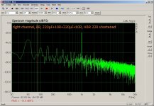
 #3 right channel, 8R, 220µF+10R+220µF+10R, HBR 22R.jpg190.9 KB · Views: 103
 -
 #2 left channel, 8R, 220µF+10R+220µF+10R, HBR 22R shortened.jpg190.8 KB · Views: 103
 -
 #1 right channel, 8R, 220µF+10R+220µF+10R, HBR 22R shortened.jpg193.9 KB · Views: 102
I need a new choke, this one was pulled from a Chinese 845 amp with known bad reputation. It was used in the GND line - I am not brave enough to try it in B+.alujoe2,
You put L6 in the ground side of the B+ circuit;
and R23, 33 Ohms in the + of the B+ side.
Yes, L6 reduces (localizes) the B+ ground loop.
But then R23, 33 Ohms puts all of the remaining ripple current (and voltage) on the top of the second filter cap, and the second cap "floats".
Try putting L6 in the B+ lead between the + of the first filter cap, and the + of the second filter cap.
Then use separate wires in the ground path.
One wire from bridge negative (-) to first filter cap negative (-).
One wire from first filter cap negative (-) to the second filter cap negative (-).
One wire from the second filter cap negative(-) to the amplifier's central ground point.
Uh, you did use a choke that has a high enough voltage rating to not arc over when B+ goes to maximum voltage before the tubes warm up and draw current.
Otherwise, get a new choke before putting it in the + side of B+.
Thank you very much for your valuable inputs !Also C1 is not very effective with R26, 22 Ohms in the circuit. Jumper across R26.
If you have bad problems with signal source ground loops, find a way to fix that outside of the amplifier circuits, not inside the amplifier circuits.
That is about all I can see at this time.
Good luck pushing the hum and noise down.
I fully agree, I need to reduce B+ hum/buzz/noise.Post #42 plots indicate that bias related hum is not noticeable, but do indicate that B+ related hum is an issue (and that includes hum ingress from the screen via the UL connection to B+).
First of all, the local feedback in UL mode is history, I went back to Triode mode. The amp is still slightly different, as there is a ECC99 as driver in the left channel and a 6N(H)6P in the right channel. Right channel with lifted caps, left channel as per schematic.If the focus turns to the B+ supply, have you done two comparison plots for just the output stage (driver coupling caps disconnected) where the base case doesn't include the choke (to provide a simpler circuit - so just filter caps and the 33 ohm CRC filter), and a step case where you add a flying 470uF cap to the B+ OT lead and the 10 ohm cathode sense resistors? You may have done those plots, but best that you pick them out.
If there was a noticeable hum drop between those two setups, then can you confirm the original 470uF capacitor that feeds the output stage is connecting to the same physical circuit locations as your added test capacitor, and the 0V link back to the power supply bridge and first filter cap is not connected to any other 0V point.
Another issue is the 2nd channel also has such a 0V node at the output stage 10 ohm sense leads, and that is going to be a hum loop situation. So can you do a comparison test where the 2nd channel has its B+ connection in place, and then with no B+ connection (ie. no circuitry or filter caps get powered, and hence no 0V link currents from that channel).
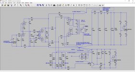
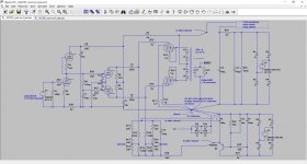
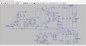
Attached find the changes I did in the two schematic drawings. The drawings are rather accurate (except input and driver, there is a left/right difference on the PCBs). Yes, there is common impedance from C14 in ver4 (C7 in ver5) to 0 V reference.
I did some measurements, but as you can see from the plots, they don't make much sense (at least for me). I noted the DMM measurements to see if the soundcard is delivering non repeatable non sense or not.
I tried to show the effect of additional RCRC 10R/220µF/10R/220µF and mitigating the common impedance by not connecting the left channel.
The effect of the choke was shown clearly earlier and I expected the RCRC to show an improvement.
What shall I do ? Proceed to the 'attach a cap to B+ and 10R' or ... please help
 .
.Attachments
-
 ver5_test.jpg260 KB · Views: 57
 -
 ver4_test.jpg241.9 KB · Views: 54
 -
 #05 right channel, 8R, 220µF+10R+220µF+10R, left channel powered, input shortened, 0.175mVRms.jpg197 KB · Views: 38
 -
 #04 right channel, 8R, no 220µF+10R+220µF+10R, left channel powered, input shortened, 0.175mVRms.jpg196.5 KB · Views: 37
 -
 #03 right channel, 8R, no 220µF+10R+220µF+10R, no left channel, input shortened, 0.226mVRms.jpg218.5 KB · Views: 40
 -
 #02 right channel, 8R, no 220µF+10R+220µF+10R, no left channel, input shortened, 0.226mVRms.jpg217.7 KB · Views: 44
 -
 #01 right channel, 8R, 220µF+10R+220µF+10R, no left channel, input shortened, 0.186mVRms.jpg197.4 KB · Views: 42
Hum is just like an Onion.
Until you remove the outer layers, you can not see the inter layers.
But then the analogy ends.
Some methods used to remove the outer layers of the hum may cause the inner layers of the hum to increase.
Until you remove the outer layers, you can not see the inter layers.
But then the analogy ends.
Some methods used to remove the outer layers of the hum may cause the inner layers of the hum to increase.
It looks like the plots in posts #51 and $#53 now include the whole amp, and with multiple changes. If so then imho they represent apples, not oranges. All I can suggest is you make a new baseline plot, with just the output stage, and no interaction from other channel, and make a plot for single change steps, as a means to clarify where and how hum is ingressing given your new arrangements.
If you are settled with baseline plots for just the output stage, then I suggest only adding one stage of the amp test channel at a time, and ensuring each new stage has a grounded input. For the PI stage that probably means inserting a high bleed resistance between the first and second stages (to provide a fixed bias), and decoupling the PI stage input to ground. For the input stage that means a temporary link from input grid to 0V end of R2.
If you are settled with baseline plots for just the output stage, then I suggest only adding one stage of the amp test channel at a time, and ensuring each new stage has a grounded input. For the PI stage that probably means inserting a high bleed resistance between the first and second stages (to provide a fixed bias), and decoupling the PI stage input to ground. For the input stage that means a temporary link from input grid to 0V end of R2.
Last edited:
NOooo, I don't want to drive you mad 😀.It looks like the plots in posts #51 and $#53 now include the whole amp, and with multiple changes.
I think I followed the rules....If so then imho they represent apples, not oranges. All I can suggest is you make a new baseline plot, with just the output stage, and no interaction from other channel, and make a plot for single change steps, as a means to clarify where and how hum is ingressing given your new arrangements.
I should have written more about the measurements.
1) The amp changed from UL including local feedback (Supertriode) to a standard triode mode setup as can be seen in the first schematic (ver4) in post #53. There are no other changes (only corrected the drawing to better show reality). The second schematic (ver5) shows the RCRC for the B+.
2) All measurements are always only relative to the first baseline plot of the individual post. Do not compare left and right channel or old and new plots, only compare left channel plots of the same post and right channel plots of the same post. I try to keep the same gain settings, but sometimes I have to adjust the gain. Never ever take the ARTA numbers as absolut numbers, as they are not calibrated. The only absolut numbers are the DMM readings.
3) There is a big difference in the noise if the inputs are shortened or if the inputs are connected to the soundcard generator.
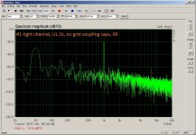
4) Regarding post #51: I wanted to see/show the influence of the HBR (R26 22R). I was assuming that the additional RCRC for the B+ as per ver5 schematic would drop the B+ noise and therefore show better the influence of the HBR. On the right channel the grid coupling caps are disconnected. Therefore (new) baseline plot for right channel (#1) and for left channel (#2) HBRs shortened, than one step to plots #3 and #4 with the HBRs not shortened and another step to plots #5 and #6, this time the inputs are shortened.
5) With the same spirit, one step at a time I tried to do the post #53 plots.
All plots are right channel, caps lifted.
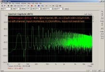
The baseline plot is - you guessed it - #1. It is/should be the same as plot #5 from post #51, except that the left channel isn't powered - B+ disconnected.
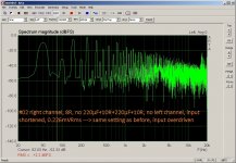
For the second plot - one step move - I disconnected the RCRC (now ver4 schematic instead of ver5) and as expected the noise increased. The soundcard indicated that the input is over driven, therefore plot #3 using reduced gain from the soundcard input to show the noise spectrum and not the clipping spectrum of the soundcard input.
Next single step to plot #4 was powering the left channel again. DMM indicated less noise than plot #1, but maybe I just have to wait a little bit longer to get an equal reading as in plot #1. This would indicate it doesn't matter in terms of noise if the left channel is powered or not - the common impedance problem from 0 V reference to C14 in ver4 schematic is not reflected in the measurement. Not what I expected, but who knows...
Next single step to plot #5 was adding the RCRC (ver5 schematic) again, same as plot #1 but powered left channel. Same reading on the DMM as in plot #4. Removing RCRC and no left channel B+ (#1 -> #2) leads to more noise, but adding RCRC with left channel B+ doesn't change anything ???
Comparing #4 and #5 leads to the conclusion RCRC is worthless, I don't believe that...
Comparing #1 and #5 leads to the conclusion, it is better to have the left channel powered, no really intuitive for me...
... therefore, must be something wrong with my thinking or measurements. Please explain ...
Thank you, will do it.If you are settled with baseline plots for just the output stage, then I suggest only adding one stage of the amp test channel at a time, and ensuring each new stage has a grounded input. For the PI stage that probably means inserting a high bleed resistance between the first and second stages (to provide a fixed bias), and decoupling the PI stage input to ground. For the input stage that means a temporary link from input grid to 0V end of R2.
Some more plots, done with the laptop and soundcard battery powered.
Again right channel, coupling caps lifted, no B+ for left channel.
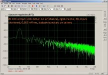
#1 using the RCRC, gave exactly the same result on the DMM as #2 without the RCRC. #3 without the RCRC, but bias cap C8 connected to HV C14 instead of 0 V reference. The other steps where moving the 10R (R11+R12) returns to C14 and the last step was moving the C2 return to C14.
In short, I was not able to show the effect of the additional RCRC in the B+, same problem as in the previous post. Still a mystery for me, why there is no change.
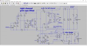
I could get rid of some common impedance issues which results in ver6 schematic. Actually I had this already some time ago, but it didn't show up in the other noise.
If I switch the amp on/off, the DMM immediately responds, which I think indicates that further improvements could be gained by increasing the distance between PT and OPT. I measured 0.077 mVrms amp off, 0.157 mVrms without tubes and 0.115 - 0.120 mVrms in the final (ver6) version.
Can someone please tell me what a good distance between PT and OPT is ?
Again right channel, coupling caps lifted, no B+ for left channel.
#1 using the RCRC, gave exactly the same result on the DMM as #2 without the RCRC. #3 without the RCRC, but bias cap C8 connected to HV C14 instead of 0 V reference. The other steps where moving the 10R (R11+R12) returns to C14 and the last step was moving the C2 return to C14.
In short, I was not able to show the effect of the additional RCRC in the B+, same problem as in the previous post. Still a mystery for me, why there is no change.
I could get rid of some common impedance issues which results in ver6 schematic. Actually I had this already some time ago, but it didn't show up in the other noise.
If I switch the amp on/off, the DMM immediately responds, which I think indicates that further improvements could be gained by increasing the distance between PT and OPT. I measured 0.077 mVrms amp off, 0.157 mVrms without tubes and 0.115 - 0.120 mVrms in the final (ver6) version.
Can someone please tell me what a good distance between PT and OPT is ?
Attachments
-
 ver6_test.jpg248.7 KB · Views: 47
 -
 #3 bias connected to HV cap, no 10R+220µF+10R+220µF, no left channel, right channel, 8R, inputs .jpg208.2 KB · Views: 38
 -
 #2 no 10R+220µF+10R+220µF, no left channel, right channel, 8R, inputs shortened, 0,165 mVrms, la.jpg201.6 KB · Views: 35
 -
 #1 10R+220µF+10R+220µF, no left channel, right channel, 8R, inputs shortened, 0,165 mVrms, lapto.jpg198.3 KB · Views: 44
For post #57, you show a schematic with C16 as the final bias filter cap, but then describe the step change as changing the location of C8, as well as making two other changes. Does that mean three changes were made for #3 plot that weren't made for #1-2 plots? Are you able to show a plot with C16 connected directly to 10 ohm cathode senses?
Are you able to show a plot with 220uF connected directly to OT B+ and to 10 ohm cathode senses? You show the B+ filtering cap positive feed being distant from the OT B+.
The above suggestions are aimed at trying to identify if your pre-existing way of connecting bias and B+ filters are somehow causing hum ingress. If they show no change, then can I suggest some photos.
As an aside, it is quite difficult to quickly interpret plots if there is no directly related schematic for each plot in the same post. That situation exists for most posts so far, and any kind of comprehension requires finding past schematics and reading multiple posts and trying to interpret what is in and out of circuit.
Is there a reason for choosing 1k screen stopper? 1k is higher than I have typically seen used.
Last edited:
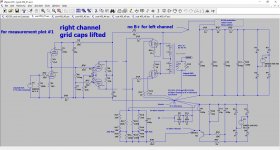
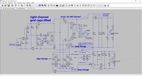
This is basically repeating post #57:
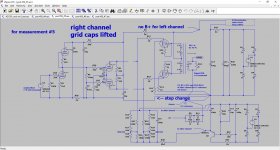
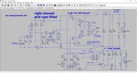
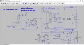
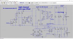
I made schematics for every step, I hope it is clear. For the first 3 schematics there is the equivalent measurement plot. For schematic 4+5 use measurement plot #3 as there is no visible difference (only the DMM tells me success).
My main(?) problem is the available space. The tubes and the PT and OPT should have more space between them. Tube orientation is wrong, there is no space for a choke, but I think I need one...
I am thinking about switching to KT120 (less THD, more deep end I have been told). Needs more heater current and 51k instead of 100k grid resistor.
Can you please tell me a reasonable f3dB frequency ?
No, again, I don't make more than one step, at least not intentional 😀.For post #57, you show a schematic with C16 as the final bias filter cap, but then describe the step change as changing the location of C8, as well as making two other changes. Does that mean three changes were made for #3 plot that weren't made for #1-2 plots?
I made schematics for every step, I hope it is clear. For the first 3 schematics there is the equivalent measurement plot. For schematic 4+5 use measurement plot #3 as there is no visible difference (only the DMM tells me success).
I don't think you want me to try schematic #6 or do you ? Is #7 what you want (it is hard to do, because of space) ?Are you able to show a plot with C16 connected directly to 10 ohm cathode senses?
My main(?) problem is the available space. The tubes and the PT and OPT should have more space between them. Tube orientation is wrong, there is no space for a choke, but I think I need one...
Yes there is quite a big distance between the 10Rs and from the 10Rs to the cap. Basically impossible to fit it in the chassis. If I do it using long wires to the outside it is senseless I guess. Are you satisfied with 1R+1µF RC ?Are you able to show a plot with 220uF connected directly to OT B+ and to 10 ohm cathode senses? You show the B+ filtering cap positive feed being distant from the OT B+.
I am sorry, hopefully you like it the way I did it for this post, if not, please tell me.The above suggestions are aimed at trying to identify if your pre-existing way of connecting bias and B+ filters are somehow causing hum ingress. If they show no change, then can I suggest some photos.
As an aside, it is quite difficult to quickly interpret plots if there is no directly related schematic for each plot in the same post. That situation exists for most posts so far, and any kind of comprehension requires finding past schematics and reading multiple posts and trying to interpret what is in and out of circuit.
Original value is 100R, but the KT88s oscillate at 650 kHz as the scope told me and I found this, therefore 1k, maybe 470 is good enough as well, didn't test it :Screen grid modificationIs there a reason for choosing 1k screen stopper? 1k is higher than I have typically seen used.
I am thinking about switching to KT120 (less THD, more deep end I have been told). Needs more heater current and 51k instead of 100k grid resistor.
Can you please tell me a reasonable f3dB frequency ?
Attachments
-
 post #59 #6.jpg272.4 KB · Views: 46
 -
 post #59 #5.jpg280.8 KB · Views: 48
 -
 post #59 #4.jpg280.8 KB · Views: 36
 -
 #3 bias connected to HV cap, no 10R+220µF+10R+220µF, no left channel, right channel, 8R, inputs .jpg208.2 KB · Views: 49
 -
 post #59 #3.jpg284.6 KB · Views: 35
 -
 #2 no 10R+220µF+10R+220µF, no left channel, right channel, 8R, inputs shortened, 0,165 mVrms, la.jpg201.6 KB · Views: 42
 -
 post #59 #2.jpg284.4 KB · Views: 38
 -
 #1 10R+220µF+10R+220µF, no left channel, right channel, 8R, inputs shortened, 0,165 mVrms, lapto.jpg198.3 KB · Views: 39
 -
 post #59 #1.jpg289.9 KB · Views: 47
 -
 post #59 #7.jpg257.5 KB · Views: 42
alujoe2,
1. I notice you list "Long Cables" from the protection relay to the center tap of the output transformer. I think long cables have lots of inductance (like at 650kHz perhaps?).
2. Did you ever calculate the Plate dissipation, and the screen dissipation of the KT88s at quiescent condition?
Can you do that, and let us know please?
3. This thread is so long, I am not sure anybody can comprehend all of it as a whole.
4. Is this the same amplifier as in your post: "What is the best/recommended way to wire the bias trim-poti ?" ?
Last edited:
- Home
- Amplifiers
- Tubes / Valves
- How can I reduce hum/noise in KT 88 PP amp?