Greetings!
I am very interested in building a Single Ended Output
Transformer-less 45 tube amplifier with the fewest parts possible. I
would be very appreciative if you could either give me some guidance.
Please excuse me ahead of time for ignorant questions but I am still learning.
What is the minimum number of tubes I would need in an OTL design? I
am okay with low power output of 1-2 watts per channel.
I did not think this was possible but in a "Boy's First Book of Electronics" a schematic was provided for a one stage amplifier with only one 1h4 power tube and no driver tube or rectifier tube. Would it be possible to drive the power tubes directly from the preamp in an iPhone instead of using the driver tubes?
Bluetooth Apple AirPods use two separate wireless channels for the L & R channel. What would I need to use one audio source (ie iPhone) and
connect to two mono bluetooth devices (one for each channel L & R)?
Stax headphones use a bias of 230v and 580v in "pro" versions. Is it possible to build electrostatic speakers that use a voltage of ~250-300v?
1H4 is not a "power" tube.
http://rtellason.com/tubedata/1H4-G.PDF
> number of tubes I would need in an OTL design?
1 Watt in 8 Ohm is 2.8V RMS or 4V peak. Which is 0.5 Amps, 500mA.
The 1H4 is good for maybe 5mA. So you need 100 tubes on top, 100 on bottom, 200 total, to make 1 Watt. It needs about 9V peak grid drive, far more than an iPod delivers.
A '45 may deliver 50mA so "only" 20 bottles. However the '45 is now very expensive.
Yes PRR I know the 1H4 its used in old 2V heater battery driven radios replaced by the smaller 1.4 heater tubes but even there the output tube -- eg- 1LA4 delivered 115mW at 5ma anode (plate ) load.
Then B7G versions later appeared still for portable battery radios.
Then B7G versions later appeared still for portable battery radios.
An OTL 45 amp that makes 1W... ok... why the 45?
We will be generous and say that you can run the 45 at 45mA. As has been said, you need half an amp peak for 1W into 8 ohms, so you will need 11 45 tubes per channel.
This project is a nonstarter.
We will be generous and say that you can run the 45 at 45mA. As has been said, you need half an amp peak for 1W into 8 ohms, so you will need 11 45 tubes per channel.
This project is a nonstarter.
I've seen some antique radio schematics but I don't know how to design one without the radio receiver.
Yes PRR I know the 1H4 its used in old 2V heater battery driven radios replaced by the smaller 1.4 heater tubes but even there the output tube -- eg- 1LA4 delivered 115mW at 5ma anode (plate ) load.
Then B7G versions later appeared still for portable battery radios.
SE OTL tube amplifier with the fewest parts possible poses several opposing requirements. In order to eliminate the output transformer, several output tubes are used in parallel to lower the plate impedance and match it to the headphones.Greetings!
I am very interested in building a Single Ended Output
Transformer-less 45 tube amplifier with the fewest parts possible.
...
What is the minimum number of tubes I would need in an OTL design? I
am okay with low power output of 1-2 watts per channel.
For example, look at the Douk Audio Vacuum Tube Headphone Amp HiFi Stereo Preamplifier which uses 24PCS 6J1 tubes.
Douk Audio 24PCS 6J1 Vacuum Tube Headphone Amp HiFi Stereo Preamplifier| | - AliExpress
Looking at the schematic, the 1H4 is powered by 45 volt batteries, thus no rectifier, and driving 2kohm headphones from the plate - think of it as the primary of the transformer.I did not think this was possible but in a "Boy's First Book of Electronics" a schematic was provided for a one stage amplifier with only one 1h4 power tube and no driver tube or rectifier tube. Would it be possible to drive the power tubes directly from the preamp in an iPhone instead of using the driver tubes?
Not sure how this question fits with the SE OTL amplifer premise.Bluetooth Apple AirPods use two separate wireless channels for the L & R channel. What would I need to use one audio source (ie iPhone) and connect to two mono bluetooth devices (one for each channel L & R)?
Do you mean electrostatic speakers or electrostatic headphones?Stax headphones use a bias of 230v and 580v in "pro" versions. Is it possible to build electrostatic speakers that use a voltage of ~250-300v?
It is possible to build Stax headphone driver circuits that use +/- 250-300v, but again, not simple, not few parts, and only suitable for electrostatic headphones.
Greetings!
I did not think this was possible but in a "Boy's First Book of Electronics" a schematic was provided for a one stage amplifier with only one 1h4 power tube and no driver tube or rectifier tube.
Hi
As you see it's not that easy but may you like to show this schematic from that "Boy's First Book of Electronics" may the one or other member here can get you further.. and since its running on low voltage, it will eventually be even more complicated.. But Go for it.,, the Idea is worth it..
I can't help you,, I have no ideas about tubes..
Regards
Chris
I've seen some antique radio schematics but I don't know how to design one without the radio receiver.
Actually pretty easy -
Split it down the middle ,ignore the RF and IF stages and look at the schematic from the AF stage onward s.
Many old radios had an input for an old ,large, mechanical record player ( 78,s only ) of the 1930,s .
In the UK a good one had a PX4 then later pentodes/tetrodes like the 6V6 (American ) or the EL range like the EL33 onwards .
Depends how far you want to go back in time.
There is a vast range to chose from .
If you were rich you had 3 stages of AF output and (in those days ) "quality " output transformers but good ones were very pricey (low leakage ) .
A top end UK company in transformers were Parmeko made transformers for the Military during WW2 including "tropicalised " versions.
As a matter of fact I have the companies spec. for its output transformers like the -
EL84
EL34
ECL82
N709
6L6
KT88
I have a Bottlehead stereomour converted to a 45 output tubes and there’s not a lot of power there 1.75wpc , but what I can tell you is that this is better than any for revealing the tone of a instrument , out of tubes that are older than most of us!!!!
Would the 45 make a good preamp tube?
Nothing is impossible but its a directly heated tube with the following disadvantages-
Vacuum Tube Theory, a Basics Tutorial – Page 4
Vacuum tube electrodes
The Cathode
There is a variety of different types of Cathode that are used in vacuum tubes. They differ in the construction of the Cathode and the materials used.One of the major ways in which Cathodes can be categorized is by the way they are heated.The first type to be used was what is termed directly heated. Here a current is passed through a wire to heat it. In addition to providing the heat it also acts as the Cathode itself,emitting the electrons into the vacuum. This type of Cathode has the disadvantage that it must be connected to both the heater supply and the supply used for use in the Cathode -Anode circuit itself. This has disadvantages because it limits the way the circuit can be biased unless each heater is supplied separately and isolated from each other. A further disadvantage is that if an alternating current is used to provide the heating, this signal can superimposed upon the main Cathode - Anode circuit, and there is a resultant hum at the frequency of the heater supply. The second type of Cathode is known as an indirectly-heated Cathode. Here the heater is electrically disconnected from the Cathode, and heat is radiated from the heater to heat the Cathode. Although as a rule it takes longer for these types of tubes to warm up, they are almost universally used because of the flexibility this provides in biasing the circuits, and in isolating the Cathode - Anode circuit from the effects of hum from the heater supply.
So if a 45 were to be used we would need DC on the filament then?
I'm just wondering because the output of the 45 is so low, yet it is said to be one of the best sounding tubes. Seems like it might make a good preamp tube then? Maybe second stage?
I'm just wondering because the output of the 45 is so low, yet it is said to be one of the best sounding tubes. Seems like it might make a good preamp tube then? Maybe second stage?
In its day it was used as an audio output tube ,in olden days tubes were inefficient and didn't output a great deal of watts ,
The highly sought after and highly expensive (now and then ) PX4 only outputs =4.5 watts .
If you were rich then you could buy the PX25=6watts,
price now =$1,200 (eBay ).
You could use DC but you have to take the circuit into consideration too.
The whole purpose of a preamp tube is----LOW noise as small amounts of noise are amplified by the preamp circuit and will appear big in the power amp.
Noise and distortion though are not the same thing but it spoils the listening quality.
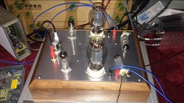
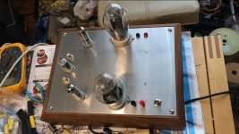
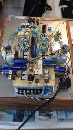
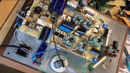
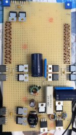
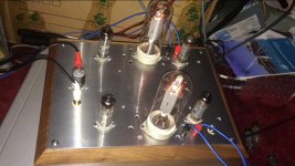
Single ended DHT Zotl amp that i have build some time ago. I tried different tubes in this amp as you can see on the images.
Attachments
You can use a 45 as a preamp tube, sure. It will help to still use an output transformer so you can step the noise down. A 10K:600 is commonly available and would work fine for this to give you approximately unity gain. DC heaters would be a must have here, with regulated DC heaters being more likely to be quiet enough.
Would the 45 make a good preamp tube?
It could .. with limited voltage swing required at the grid you could take advantage of the lower Rp afforded by less bias. Say 180V, -31V, 31mA and 1650 ohm Rp, straight from the data sheet.
Specifying transformer by impedance ratio is close to meaningless, go with something like:
45H Lpri: -1dB at 22Hz, -3dB at 6Hz
4:1, Zout 100 ohm, Av 0.875
2:1, Zout 400 ohm, Av 1.75
1:1, Zout 1650 ohm, Av 3.5
Select which fits best, for loads >20k ohm, I would look to 1:1.
HK
Last edited:
I've seen some antique radio schematics but I don't know how to design one without the radio receiver.
Most radios "split" at the volume control. Take the wire off the top of the volume pot and run it to an input jack (see attached). Then the tuner part is not used and may be omitted.
That's the basic. In real life most radios interweave B+ feeds and heater feeds so they may not work simply chopping-out the tuner. And many low-price radios lack galvanic isolation from the power line, and become un-safe when you add user-touchable audio connectors.
Attachments

Here is relatively modern tubes noise measurements , take into consideration we are dealing with a ,20,s designed output tube which uses part of the heater circuit as its cathode .
Here are test circuits simple to build for tubes to test for noise levels inherent in the design.
I am all for experimentation in fact I encourage it but we are dealing with very old technology in tube design.-
Audio Tube Noise Measurements – Tavish Design
I am sure this will be of relevance to some here.
Greetings!
I did not think this was possible but in a "Boy's First Book of Electronics" a schematic was provided for a one stage amplifier with only one 1h4 power tube and no driver tube or rectifier tube. Would it be possible to drive the power tubes directly from the preamp in an iPhone instead of using the driver tubes?
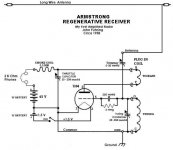
Is this similar to the schematic in your book? Please note that the 1H4 is powered by 45 volt batteries, thus no rectifier, and driving 2kohm headphones from the plate - think of it as the primary of the transformer.
Attachments
In actual fact its a misnomer to class the 1H4 as a "power tube " while it might look like that when powering an old large tube portable radio its output is at most =200mw.
In fact all the tube equivalent books I have class it as an -amplifier triode which would originally be designed ( if used in mains equipment ) as driving an output tube but it was used extensively in portable tube radios long ago.
That,s why Kornelux,s circuit diagram shows 45V DC batteries which were used as "HT" for many of those radios , 90V "HT" DC batteries were also used in many designs .
The Regenerative design shown is familiar to me and is an easy way to introduce simple radio/wireless circuits to beginners ,you adjusted it till it started to oscillate and thereby picked up radio signals .
Because it was only one tube ( an advancement on an early crystal set ) like the crystal set it needed a very long aerial usually strung ( with ceramic insulators ) between a tree in your garden (high up ) and the wall of your house.
- Home
- Amplifiers
- Tubes / Valves
- Single Ended 45 Amplifier