Greetings:
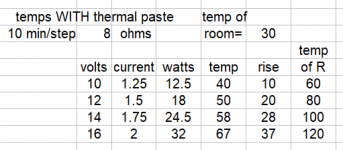
I couldn't find a better place to put this (but if there is, let me know), so here it is. I have a copper finned heatsink and am trying to figure about how much heat it can dump. My attempt included sanding smooth the bottom of an 8 ohm power resistor and using some CPU thermal paste to transfer as much of the heat into the heat sink. The attached table (below) shows what temperatures I saw.
The big issue is trying to figure out how much of the wattage generated by the resistor was transferred to the copper, and how much was radiated by the resistor directly to air. Note that a LOT of heat was being transferred to the room. The ambient temperature in the room had bumped up to 30C at the time of this test run (it was 104F outside).
I'm hoping to use the sink for a MoFo, but I'm concerned that it can't quite sink enough. I am also considering using two, and having them brazed together at an angle with a triangular block of copper to give the brazed parts strength, a solid copper bridge to spread the heat, and use it as a base to mount the MOSFET on.
Any thoughts on how much of the 32W going into the resistor are actually going into the copper heat sink? Once that is answered, the C/W should be easy enough to calculate...
Attachments
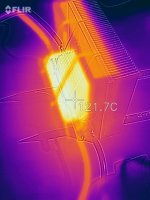
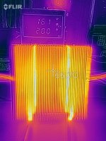
Here are two thermal scans of the setup, including the very hot resistor and the much cooler copper. Don't be confused by the color, it auto-ranges. The purple thing in the background of the second shot is the power supply showing 16.1v at 2.0A, for roughly 32W into the resistor... But how much went into the heat sink?
The hot lines are the fins with cotton string that was used to help hold the resistor in place on the back of the heat sink so it could be in the most advantageous orientation. Cotton is not a good conductor of heat, it turns out. 😀
The hot lines are the fins with cotton string that was used to help hold the resistor in place on the back of the heat sink so it could be in the most advantageous orientation. Cotton is not a good conductor of heat, it turns out. 😀
Attachments
If, 32W dissipation makes 37K temperature increment, then the heatsink is 37K/32W=1,15K/W. This is of course a bit rough counting, but can be OK in practice. To stay on a safe side, calculate with 1,5K/W.
The temperature difference is 121-67=54K, which means, that the case to sink thermal resitance is 1.6875K/W.
If you want to know the thermal resistance of the resistor itself, just heat it up, without heatsink. Just with -say-, 5W, and You can calculate the resistor to air thermal resistance too.
Sajti
Last edited:
Copper evenly distributes heat than aluminum. Air cooling depends on the area of the radiator, the location of the fins and the permissible temperature. Forced air cooling (as in the computer) depends on the air speed of the fan.
Your heatsink is designed for forced air circulation and without it is very far from its maximum efficiency.
To eliminate heat transfer from resistor directly into a room, thermally insulate the resistor by simply putting piece of packing foam over it. Half inch foam will cut heat transfer directly to the air to nearly 5%. Even a piece of cardboard preventing air circulation around the resistor will cut it by 80%-90%The big issue is trying to figure out how much of the wattage generated by the resistor was transferred to the copper, and how much was radiated by the resistor directly to air.
Last edited:
Here are two thermal scans of the setup, including the very hot resistor and the much cooler copper. Don't be confused by the color, it auto-ranges. The purple thing in the background of the second shot is the power supply showing 16.1v at 2.0A, for roughly 32W into the resistor... But how much went into the heat sink?
The hot lines are the fins with cotton string that was used to help hold the resistor in place on the back of the heat sink so it could be in the most advantageous orientation. Cotton is not a good conductor of heat, it turns out. 😀
You are misinterpreting this picture I think. Bare metal is very poor at radiating heat, I think you have an anodized resistor (very good at radiating) bonded to a bare metal heatsink. The cotton radiates efficiently (most materials do, just not bare metals).
Looking into the fins shows up as warmer due to the fact that a hole in a box is a more effective black body.
I appreciate the comments, but I know and understand all that. This is as much an art project (WAF) as it is an amplifier part, so untreated copper is required.
The question I am asking is simple:
Of the 32W the resistor is generating, how much is going into the heat sink and how much is leaving the resistor directly?
I don't need an exact number, just looking for a ball-park figure. Is it 20/80 for resistor/heatsink? 50/50? I'm just trying to figure out how well it will work at dissipating 25W or so from a MOSFET, or if it should be abandoned entirely, as the cooling is far below being adequate.
The main (all) power is dissipated by heatsink due to cooling by air flow.
Your heatsink with nearby fins requires a fan. The geometry of the heatsink is poorly suited for free cooling.
Your heatsink with nearby fins requires a fan. The geometry of the heatsink is poorly suited for free cooling.
Thermally insulate the resistor if you want to measure the heatsink's performance, or guess that the heat dissipation scales with approximate size, so that the heatsink will be dissipating about 27W, resistor 5W. The heatsink has a lot more area and fins, but its not radiating much, and the resistor is. However convective heat loss is likely fairly dominant.The question I am asking is simple:
Of the 32W the resistor is generating, how much is going into the heat sink and how much is leaving the resistor directly?
Another thing you can do is heat the thing up, detach the resistor and monitor the temperature as it falls - the initial slope of the temperature graph on cooling will give the dissipation (once you calculate the heat capacity from the weight of the heatsink and the properties of copper).
The copper heatsink removes heat evenly.
But he himself is cooled by an air stream with poor thermal conductivity and heat capacity.
But he himself is cooled by an air stream with poor thermal conductivity and heat capacity.
Mark - Thanks. That is about what I was looking for. I have access to a heatsink roughly twice this size, and if it's about a 5:1 ratio, the larger sink will be big enough. Even a 2:1 ratio will work, but just barely.
OldDIY (and many others) - yeah, it's not the best heatsink design for a free-air setup (short, close fins), but it is sufficiently pretty for the wife, so it's what I get to use. 😉
Thanks to everyone for chipping in, and feel free to continue to add to the conversation. More ideas make for better conversations.
- Home
- Amplifiers
- Solid State
- Heat Sink question...