I am currently assembling a solar-powered boom-box, and I stumbled on a problem.
Chances are that this particular problem also worries other people, which is why I post my solution now (using commodity components, as always).
If the 450mV are still an issue, the only solution is to use a synthetic diode, based on a low-Rdson MOSfet:
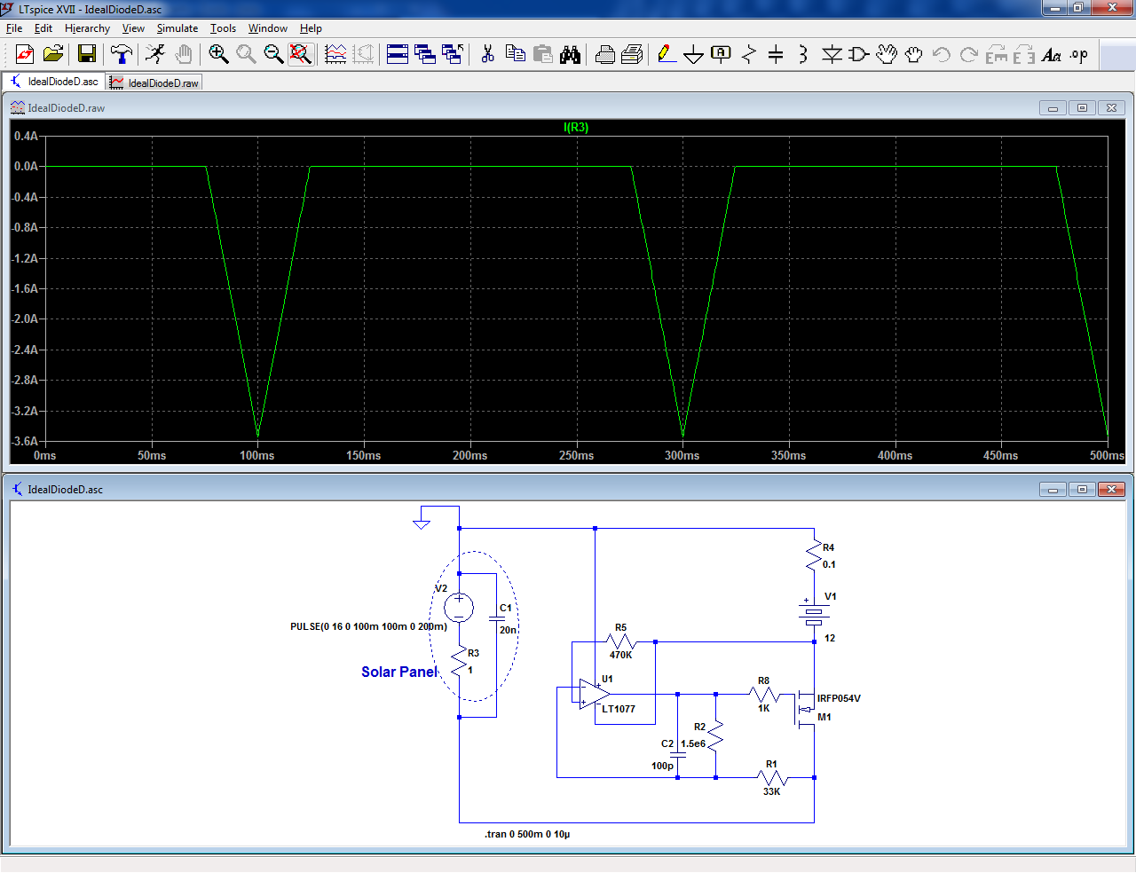
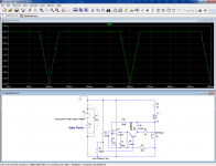
(The input is swept from 0 to 16V to simulate any condition)
It works well, and can achieve arbitrarily low-losses, but in my case there is a problem: the control opamp is supplied permanently by the battery, and if the box spends most of its time idle inside a cupboard (which it will in my case), it will drain out the battery unless it is a super-micropower one.
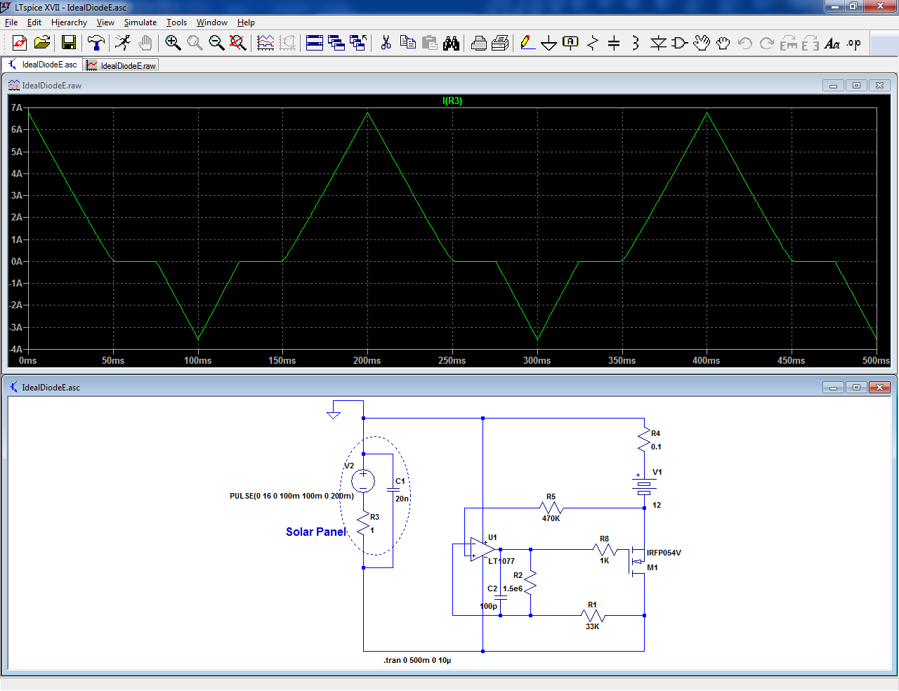
To avoid this problem, the negative supply can be tied to the input, but this creates another problem: when the negative supply is not negative enough, it cannot keep the MOS out of conduction, resulting in a high reverse current (won't be that high in reality, but still an issue):
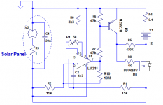
The solution I found was to add an additional turn-off transistor that keeps the MOS off if the input is not negative enough:
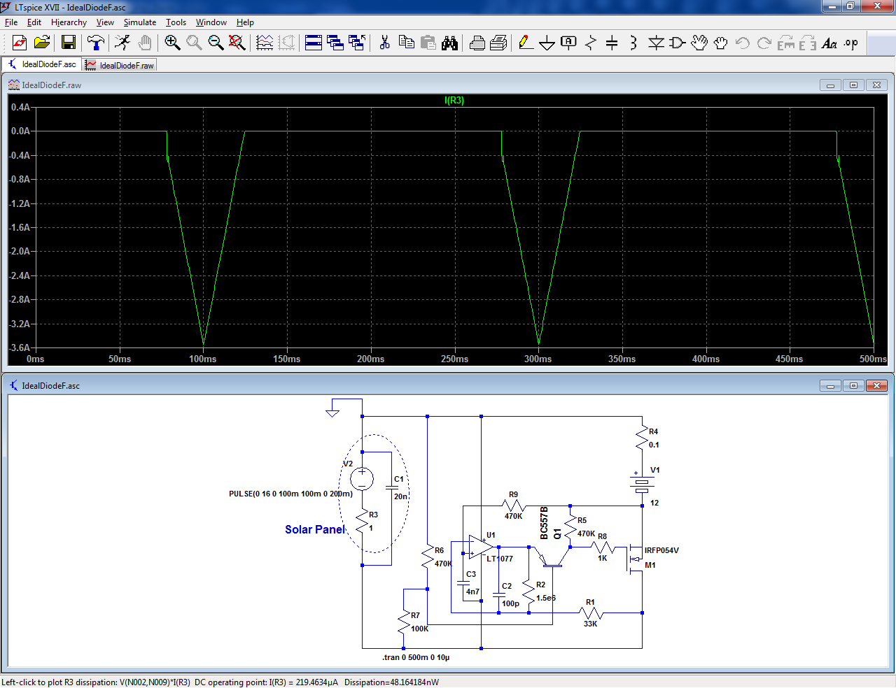
With this circuit, the only current (apart from leakages) is caused by the protection resistor R9 and the input substrate junction, and R9 can be made as high as required (in my case, 470K is sufficient to make the leakage negligible).
The sim uses a LT1077, but the circuit has been tested with a CA3160 and a TLC271. Any opamp having GND in its common-mode range should work equally well.
Chances are that this particular problem also worries other people, which is why I post my solution now (using commodity components, as always).
- The initial problem:
When you use a simple, direct charging connection between the solar panel and the battery, you need to insert a blocking diode, to avoid discharging the battery into a dark panel (the equivalent Is of solar cells is huge).
An ordinary Si diode is fine if you tolerate 0.9V drop.
A schottky diode is about 2x better (but has a significant leakage).
If the 450mV are still an issue, the only solution is to use a synthetic diode, based on a low-Rdson MOSfet:
(The input is swept from 0 to 16V to simulate any condition)
It works well, and can achieve arbitrarily low-losses, but in my case there is a problem: the control opamp is supplied permanently by the battery, and if the box spends most of its time idle inside a cupboard (which it will in my case), it will drain out the battery unless it is a super-micropower one.
To avoid this problem, the negative supply can be tied to the input, but this creates another problem: when the negative supply is not negative enough, it cannot keep the MOS out of conduction, resulting in a high reverse current (won't be that high in reality, but still an issue):
The solution I found was to add an additional turn-off transistor that keeps the MOS off if the input is not negative enough:
With this circuit, the only current (apart from leakages) is caused by the protection resistor R9 and the input substrate junction, and R9 can be made as high as required (in my case, 470K is sufficient to make the leakage negligible).
The sim uses a LT1077, but the circuit has been tested with a CA3160 and a TLC271. Any opamp having GND in its common-mode range should work equally well.
Attachments

Why not use the voltage drop on the connection panel-fet drain ?
And a little hysteresis ~20mV.
Mona
And a little hysteresis ~20mV.
Mona
Attachments
Last edited:
A boombox does not usually have a high power like large public address amplifiers. Therefore, a few watts lost at a reverse current blocking diode should be tolerable.
Well, the only non-steampunk solution then (I suspected that someone would dig out that one)> the only solution is to use a synthetic diode, based on a low-Rdson MOSfet
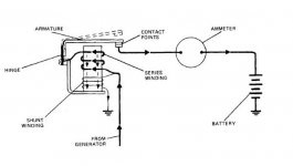
For 50 years, the standard reverse-current cut-out on automobile generators was a relay.
It is a possibility, but it would require a serious current to operate reliably.Why not use the voltage drop on the connection panel-fet drain ?
And a little hysteresis ~20mV.
Mona
The state-of-the-art solution I showed first (which I didn't create) uses the opamp in linear mode, to keep the MOS in control, even at very low currents.
The feedback keeps the MOS dropout at a more or less constant voltage, whatever the current: it is the threshold voltage multiplied by the resistive divider ratio.
The advantage is the absence of a minimum current, the drawback is that it imposes some arbitrary dropout, but at low currents the dropout has less importance, and the circuit is generally very well-behaved: no risk of hickup or flapping
In my case, the voltage of the solar panels is really marginally sufficient without losses, and adding another one would be a waste. This is why I preferred the more complex solution.A boombox does not usually have a high power like large public address amplifiers. Therefore, a few watts lost at a reverse current blocking diode should be tolerable.
There's another pretty good solution borrowed from the protection circuit in a Raspberry Pi, and I'm sure many other places. The main pass element is a P channel MOSFET It uses two PNP small signal transistors in sort of a current mirror configuration so that if the input voltage is greater than the load voltage the gate of the MOSFET is pulled low and if it's lower the gate is connected to the source via a resistor so the FET is off and the body diode is reverse biased.
I can probably sketch the circuit if it is of interest.
I can probably sketch the circuit if it is of interest.
Yes, that would be interesting (I would invert the polarities, but the principle remains the same)
ideal diode implementation
Here's the circuit I was referring to. The only caveat is to stay within the rated gate-source voltage.

Here's the circuit I was referring to. The only caveat is to stay within the rated gate-source voltage.
> the only solution is to use a synthetic diode, based on a low-Rdson MOSfet
For 50 years, the standard reverse-current cut-out on automobile generators was a relay.
True steampunk solution 🙂
Very clever and useful circuit. The real caveat is not the Vgs rating: it can be protected with a zener, but for voltages >6V, the Veb rating of the transistors will be exceeded.Here's the circuit I was referring to. The only caveat is to stay within the rated gate-source voltage.
View attachment 851383
A fix is possible: add diodes in series with the emitters, but they will reduce the accuracy and make the transition region softer.
But ideal diodes _are_ commodity components... You can get ideal bridge rectifiers too. Not too wide a choice alas.
For me, a commodity is a component directly interchangeable with many second-source alternatives, like the LM317 or the TBA820.
I do not know if many ideal diodes chips meet that criterion, and among those chips, I do not know whether they meet my requirements of leakage current etc, or not
I do not know if many ideal diodes chips meet that criterion, and among those chips, I do not know whether they meet my requirements of leakage current etc, or not
In general, the specs mimic the original, with sometimes a minor improvement here and there (advertised), and also less flattering differences (swept under the carpet).Question is if one can expect highest/lowest specs from commodity parts
The NE5532's from TI, Signetics or JRC will all work in the same circuit, with some minor performance difference
- Home
- Amplifiers
- Power Supplies
- An improved "Ideal Diode"