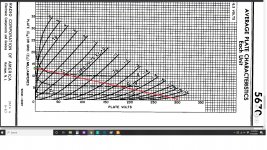

Now looking at what's remaining to the right of the vertical line, that's the area you can operate in. You want to look for even spacing between the grid voltage lines along your load line. This looks horrible way over to the right, and that's OK, we can just operate further over to the left.
The spot where plate voltage is about 140V, current is about 8mA, and bias voltage is about 2V looks good.
The spot where plate voltage is about 140V, current is about 8mA, and bias voltage is about 2V looks good.
You're going to be able to swing down from 145V to 90V before you hit the 0V grid line. That's 55V peak or just under 40V RMS. This is plenty of swing for a preamp.
You have 2V of bias and 8mA of current. Back to Ohm's Law V=I*R so 2V=0.008A*R, so R=2/0.008 or 250 ohms.
You have 2V of bias and 8mA of current. Back to Ohm's Law V=I*R so 2V=0.008A*R, so R=2/0.008 or 250 ohms.
An externally hosted image should be here but it was not working when we last tested it.
We will borrow from another similar design to illustrate where things go.
The 33K/2W plate load in this schematic would be your 22K resistor. 8mA goes through it, so P=(I^2)*R, so dissipated power is 1.4W, so I would make it a 5W resistor so it lasts. You may need to look at values between 20K and 25K. This is OK. You aren't building a spacecraft.
The 2.2K cathode resistor on the first stage we have calculated to be 250 ohms. You don't need the bypass cap.
For the cathode follower section, we know the voltage at the grid will be about 145V from the previous stage, and the cathode will be just slightly above that, call it 150V. If you use a 22K resistor from cathode to ground, that'll get you 7mA of cathode current, which is fine. This goes in place of the 24K/3W part in the drawing.
Nice try. What you're doing here is giving basic lessons in tube amp design in plenty of postings. But thats not the aim of an audio forum.
If someone has zero knowledge in audio design a forum cannot teach him the basics in a one hundred postings. HE has to learn and read some books by himself. Thats the way to go. And there he will find all this very usefull basic informations.
I don't think a forums intention is to do such a basic learning course and it bores everyone to death who has done its homework.
But today people think others have to teach them the basics, they don't have to do anything. Completely wrong intention to participate on an audio forum.
The heater of the 5670 can only be 100V positive or negative with respect to cathode, so the low voltage winding that makes the tube glow must not be at DC ground. I would put it right at 75V.
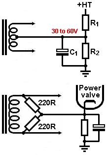
This is borrowed from Merlin's website but shows what this looks like. You have 300V or so of B+, so you need 1/4 of that. A 100K resistor from ground to the heater winding and a 300K resistor from B+ to the heater winding will accomplish this.
This is borrowed from Merlin's website but shows what this looks like. You have 300V or so of B+, so you need 1/4 of that. A 100K resistor from ground to the heater winding and a 300K resistor from B+ to the heater winding will accomplish this.
Really? Why?But thats not the aim of an audio forum.
Really? Why?If someone has zero knowledge in audio design a forum cannot teach him the basics in a one hundred postings.
Really? Why?HE has to learn and read some books by himself. Thats the way to go.
Then don't post in this thread. Participation is optional. Being rude to new people is a good way to kill the hobby.I don't think a forums intention is to do such a basic learning course and it bores everyone to death who has done its homework.
Completely wrong intention to participate on an audio forum.
Isn’t it diyaudio.com ????
And then let's make it work not only in theory, but also in practice, by adding the grid leak resistor and probably also the grid stoppers 😀An externally hosted image should be here but it was not working when we last tested it.
We will borrow from another similar design to illustrate where things go.
The 33K/2W plate load in this schematic would be your 22K resistor. 8mA goes through it, so P=(I^2)*R, so dissipated power is 1.4W, so I would make it a 5W resistor so it lasts. You may need to look at values between 20K and 25K. This is OK. You aren't building a spacecraft.
The 2.2K cathode resistor on the first stage we have calculated to be 250 ohms. You don't need the bypass cap.
For the cathode follower section, we know the voltage at the grid will be about 145V from the previous stage, and the cathode will be just slightly above that, call it 150V. If you use a 22K resistor from cathode to ground, that'll get you 7mA of cathode current, which is fine. This goes in place of the 24K/3W part in the drawing.
Also something worth noting is that you could simply use the 5670 as a pure cathode follower and use something like a 1:4 step up input transformer.
The cathode follow will have almost no input capacitance, so you can get away with a higher step up ratio without loosing any high frequencies.
Good step up transformers are kind of pricey, but since you live in europe, I am sure you can find a decent pair of lundahls or sowters for cheap.....ish.
If that is something you can do for cheap, it's certainly worth consideration.
And then let's make it work not only in theory, but also in practice, by adding the grid leak resistor and probably also the grid stoppers 😀
Grid stoppers, maybe.
But I do not believe you need grid leaks in this circuit. The volume knob is your grid leak for the first tube and since the second tube is directly connected, you don't use a grid leak on the second tube.
Audiowize
Excellent explanation/tutorial. You made it simple.
I saved your posts and images to a word doc for future reference.
Steve
Excellent explanation/tutorial. You made it simple.
I saved your posts and images to a word doc for future reference.
Steve
Nice try. What you're doing here is giving basic lessons in tube amp design in plenty of postings. But thats not the aim of an audio forum.
If someone has zero knowledge in audio design a forum cannot teach him the basics in a one hundred postings. HE has to learn and read some books by himself. Thats the way to go. And there he will find all this very usefull basic informations.
I don't think a forums intention is to do such a basic learning course and it bores everyone to death who has done its homework.
But today people think others have to teach them the basics, they don't have to do anything. Completely wrong intention to participate on an audio forum.
Actually I think the opposite, but everyone is free with their own opinions.
I have a degree in chemistry and for some years now I have been delighting in electronics: I think I have learned more here than from books.
Let me explain better, of course books are needed but as Audiowize says in a forum you can find the incentive to increase your curiosity, and the desire to experiment. And then the straightforward language is often more understandable than certain abstruse texts.
Sorry if I came out of the seed a bit 😛
Relying on the pot itself when providing the 0V reference to the grid is very bad practice. Pots fail. Even the best ones. In fact, they "micro-fail" tens or hundreds of times every time you adjust the volume.The volume knob is your grid leak for the first tube
When it comes to grid stop resistors I have read that 100 ohm is all that is really needed so why do we usually see 1K?
Actually I think the opposite, but everyone is free with their own opinions.
I have a degree in chemistry and for some years now I have been delighting in electronics: I think I have learned more here than from books.
Let me explain better, of course books are needed but as Audiowize says in a forum you can find the incentive to increase your curiosity, and the desire to experiment. And then the straightforward language is often more understandable than certain abstruse texts.
Sorry if I came out of the seed a bit 😛
I agree because I have found that basic theory books do very little to educate design principles. Grid leak resistors for example, the theory books tell me why I need one and show a few example values, but it wasn't till I got here that I was educated on the fact that the value is determined by the tube used, impedance required and the frequency roll off created by interaction with the tube. That led me to research that further.
It depends on the tube, on its operating point, on the stage topology and on where you want the UHF rolloff frequency to be.When it comes to grid stop resistors I have read that 100 ohm is all that is really needed so why do we usually see 1K?
What is Miller Capacitance?
- Home
- Amplifiers
- Tubes / Valves
- Simple 5670 tube based line stage design help