.....
So I now have time to return to working on some of this and just want to put all those parts to use, so they don't set in a box for another 20 years. I know this isn't the most optimal design, I just want it to work the best IT can for what IT is. Perfect is the enemy of good...
Interesting to hear your journey with tubes to the present day. I now understand why you want to use what you have and get the best out of it.
Given your power transformer with 300-0-300 Vac secondaries, and the Hammond 1608 output transformers that are rated for 10 watts, I suggest that you limit your B+ voltage to suit 10 watts output by using a tube rectifier, with possibly a psuedo choke-input filter. Simulating the behaviour using Duncan Amp’s PSUD2 program will allow you to make good choices for component values.
Ok I think this works better
Looks better. Keep in mind you have 59V RMS x 0,365mA RMS over that resistor, which means you need a 25W power resistor (somewhere with air around it or the chassi bolted type). Or with that value and power, better with two 330 ohm 15W in parallel (easier to find and better for heat dissipation). I would use two RC filters in series (two 82 ohm power resistors or higher if needed) with the benefit of better regulation (but that's me).
So I got it done, but having problems. All I get is a very faint highly distorted sound. Originally had a Hammond 272HX, but the B+ was too high, so I got an Antek toroidal that gave me 275v-0-275v, so now B+ is closer, 317VDC. I also went back through the original schematic and changed a few resistor values, it seems the PCB had values for 6SL7/6V6 vice the 12AX7/EL84, but that didn't help, still get the same results. Any Ideas????
Attachments
So I got it done, but having problems. All I get is a very faint highly distorted sound. Originally had a Hammond 272HX, but the B+ was too high, so I got an Antek toroidal that gave me 275v-0-275v, so now B+ is closer, 317VDC. I also went back through the original schematic and changed a few resistor values, it seems the PCB had values for 6SL7/6V6 vice the 12AX7/EL84, but that didn't help, still get the same results. Any Ideas????
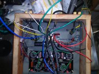
Brother, I don't know any other way to put it but you have some genuinely bad soldering on so many points on the board. At least the photos look that way, the tube sockets need to be especially well done because they take abuse of tubes in and out. You need smooth and shiny soldering that is not in question.
Ok I'll go back over it all and resolder. Thanks!Brother, I don't know any other way to put it but you have some genuinely bad soldering on so many points on the board. At least the photos look that way, the tube sockets need to be especially well done because they take abuse of tubes in and out. You need smooth and shiny soldering that is not in question.
BJ, it might be a good idea to check voltages - first without tubes, then with tubes; at least anode and cathode voltages, as well as screen for the power tubes. Measure the bias voltages. Calculate the current through the power tubes. That should give you clues as to where there might be problems. If still baffled report back and we will collectively try to figure it out.
Good luck.
Good luck.
Ok I'll go back over it all and resolder. Thanks!
Anything getting resolved with this?
Anything getting resolved with this?
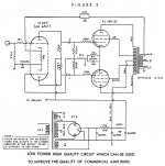
Yes I went through and resoldered everything. I made measurements and was trying to get it on a schematic. Basically I see a B+ of about 320 VDC. I just have a few volts less, about 316 VDC on the plates to the 12AX7. There is a 6.8k ohm resistor that I don't seem to be getting much voltage drop from. I had 5VDC on the cathodes of the 12AX7 and 10 VDC on the EL84. Attached is the original schematic, mine is different in the power supply, I have 2 diodes (BYT-78) and 220uf 160ohm CRC. I'm thinking maybe I burned my tubes when I first tried because I had way too much B+ (~400VDC). So not really sure.
Attachments
Oh and on the EL84 the screen voltage is just a couple volts higher than the plate voltage consistently.
Yes I went through and resoldered everything. I made measurements and was trying to get it on a schematic. Basically I see a B+ of about 320 VDC. I just have a few volts less, about 316 VDC on the plates to the 12AX7. There is a 6.8k ohm resistor that I don't seem to be getting much voltage drop from. I had 5VDC on the cathodes of the 12AX7 and 10 VDC on the EL84. Attached is the original schematic, mine is different in the power supply, I have 2 diodes (BYT-78) and 220uf 160ohm CRC. I'm thinking maybe I burned my tubes when I first tried because I had way too much B+ (~400VDC). So not really sure.
The high plate voltage on 12ax7 tells me it's not conducting. You must have a complete cathode circuit back through that 1K (1000) ohm feedback resistor and the connection through the transformer to a hard chassis ground on the speaker terminal (C) grounded. All points must be soldered well. Tube sockets especially. Grounded connections have to be solid if it's just a screw and nut to the chassis.
Last edited:
The picture you have seems to show missing FB lines down in the corners. Are you missing to lines to the speaker jacks?
Ok, thank you, I don't have it wired that way. I am using Hammond 1608 Hammond Mfg. - "Classic" Push-Pull - Tube Output Transformers - (1608 - 1620, 1645 & 1650 Series) so I will hook up the black + black/yellow (4 or 8 ohm) to ground and give it a try. I really appreciate your help.The high plate voltage on 12ax7 tells me it's not conducting. You must have a complete cathode circuit back through that 1K (1000) ohm feedback resistor and the connection through the transformer to a hard chassis ground on the speaker terminal (C) grounded. All points must be soldered well. Tube sockets especially. Grounded connections have to be solid if it's just a screw and nut to the chassis.
The picture you have seems to show missing FB lines down in the corners. Are you missing to lines to the speaker jacks?
No I have the FB lines in, that was an early pic, sorry.
The picture you have seems to show missing FB lines down in the corners. Are you missing to lines to the speaker jacks?
They are connected to the "negative" speaker jack (black/black yellow on the OPT)
They are connected to the negative speaker jack (black/black yellow on the OPT)
The (-) speaker jack needs the hard ground and the FB line goes to the (+) side.
The (-) speaker jack needs the hard ground and the FB line goes to the (+) side.
Got it, correction I do have the FB on the + OPT/ speaker jack(will double check though) BUT I don't have the - grounded. I'll add a ground wire and report back.
Ok, that was a big change! Still not working, but making an extremely loud noise, kinda starts at a high frequency just as it is turned on and then goes to a low frequency with a loud buzzing sound. Will see what is going on voltage wise latter tonight.
Ok, that was a big change! Still not working, but making an extremely loud noise, kinda starts at a high frequency just as it is turned on and then goes to a low frequency with a loud buzzing sound. Will see what is going on voltage wise latter tonight.
Well you had a 50-50 chance of that happening. So one more thing to do is get the phase swapped on the primary side of the output tranny. If you have the secondary lead colors going to the correct terminal, then you have the leads going from the tubes to the primary swapped phase-wise and those will need to go to the opposite tube. Put the plate lead and screen lead over to the other tube. Then you should have a silent amp. Right now you have positive FB.
Last edited:
- Home
- Amplifiers
- Tubes / Valves
- PP EL84