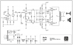
Looks like a sort off capacitance multiplier.
The decoupling capacitor doesn't get extra charge from the higher tube current but has still a charge current to maintain the 0,6V to make the transistor conduct.
Mona
I've used both bias boards and own circuits for this. The circuit you have would need changes for modern PNP silicon devices you would not need the NTC with these.
Last edited:
Thank you for the beautiful circuit. If I understand right, when output power increased the fixed bias voltage will decreased and power tube current increased, is this used to prevent crossover distortion and keep idle current low? Thanks.
Exactly.
The aim of fixed bias is to stop the decrease in bias current when you get to the class B part of the curve. Here each valve conducts more on average (watch the blue glow) and this tends to increase the average cathode voltage in self bias reducing the idle bias current causing crossover distortion.
Fixed bias needs adjustment for the valves fitted. You can put 5W zeners in the cathode + resistor to help in the self bias case.
The aim of the servo bias is to try and keep the idle current constant independent of the tube fitted and the temperature. By measuring the current through the cathode resistor and trying to keep this constant. Obviously the audio needs to be removed with a very low pass filter. The problem occurs when we get to big signals and class B part of the curve. Then a number of tricks have to be played to 'guess' the idle current. The circuit you have mixes a bit of the other cathode in to help with this. Another approach is to clip the cathode at 2x cathode idle voltage.
The servo approach can have problems at warmup as it can take grid voltage too too positive. Its best to prevent the servo circuit generating a grid voltage much above the worst case bias voltage and/or have a timer to hold the grid voltage negative for a bit.
Hope this helps.
Last edited:
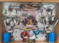
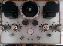
I had try the dynamic self bias on my home built dyna clone amp with big improved on output power. My self bias amp output around 25W before clipping, after I built the dynamic bias circuit, the output improved a lot to more than 46W with EL34, cathode voltage around 37 to 40 Volt. I try 6550 the cathode voltage around 47 to 50 volt and output around 43W before clipping. Don't need to doing anything when replace different output tube, I even try 5881 tube and it works good also with cathode voltage around the same as EL34 but maximum output a little bit lower.
Attachments

pwgtang,
Your schematic has g1 resistors of 100k.
The maximum g1 grid resistor for the 6550 when in fixed bias circuits is 50k Ohms.
Even in self bias, the maximum g1 grid resistor is 100k Ohms.
You are using 200k Ohms.
Wow!
Be sure your electronic auto-bias circuits will keep the 6550 from red-plating under any conditions of quiescent and signal conditions.
The EL34 has a much higher specified maximum g1 grid resistance than the 6550.
Your mileage may vary.
Last edited:
Interesting circuit the transistor conducts if the current in the capacitor goes beyond .65/10 = 65ma bringing the cathode voltage down. more like a zener but only on the AC part of the waveform.
Last edited:
6A3sUMMER
Because I want to used EL34 tube also, so I think 200K is about middle value for 6550 and EL34. I don't see red plate yet even the amp is on for few hours,
I will check this at night when I turn off all lamp.
Because I want to used EL34 tube also, so I think 200K is about middle value for 6550 and EL34. I don't see red plate yet even the amp is on for few hours,
I will check this at night when I turn off all lamp.
pwgtang,
It seems like your circuit in post # 7 is a variation of self bias.
If you use 100k g1 resistor, it will be OK for the 6550.
Of course the EL34 can work with up 500k, but 100k would almost certainly burn out the 6550s, and perhaps take the output transformers and/or the the B+ secondary with them.
Of course, your 12AU7 driver tube has to drive 100k g1 resistors.
Be sure to remember, EL34 pentode suppressor screen is not internally connected to the cathode.
You have to wire Pin 8 to Pin1 on the tube socket.
Or, you can use a KT77 beam power tube, and do not have to wire from pin8 to pin1.
Other than that needed connection from pin8 to pin1, the EL34 Pentode and KT77 beam power tube are nearly identical (suppressor screen, versus beam formers).
Last edited:
baudouin0
I had monitor the ac power consumption, when output below 10W, the ac power consumption stable, when output power above 10 W, ac current start increased, but the cathode bias voltage still maintain only few volt change even to full power output with 10 ohm.
I had try 5 ohm the cathode bias voltage will not maintain at idle voltage
when output above 10W to full power the cathode bias voltage start increased to munch and I can see cross over at full power,with 20 ohm the cathode bias voltage will decreased to munch ac power increased a lot. The 10 ohm valve is critical, it maintain the cathode bias voltage from low output to full power output. so I think the transistor is working.
6A3sUMMER
The output transformer are so expensive now, I always put a .5A fuse from transformer to B+ to protect
the transformer, because I like to try different circuits.
The output transformer are so expensive now, I always put a .5A fuse from transformer to B+ to protect
the transformer, because I like to try different circuits.
If you measure the grid voltage to ground after leaving it on it will give a good indication of whether you have an issue. Let us know what you get for each 6550. You are in self bias mode so grid voltage << cathode voltage.
Add a reverse diode from the CT of the OPT to ground. This will stop the voltage going down to -Kv if the fuse blows otherwise you may get a sustained arc in the fuse.
Add a reverse diode from the CT of the OPT to ground. This will stop the voltage going down to -Kv if the fuse blows otherwise you may get a sustained arc in the fuse.
Last edited:
- Home
- Amplifiers
- Tubes / Valves
- Dynamic cathode bias stabilization