OK, that actually makes sense electrically... but the circuit shows a conventional vbe multiplier 😉
What I think they are doing based from what you describe is using the base/emitter junction as a diode and connecting it in series with the other two diodes. That allows the transistor 'diode' to be heatsink mounted and (in theory) hold the bias constant.
Its very hit and miss and totally dependent on the device characteristics. I think wiring it as shown in my little diagram (the transistor, one resistor and the preset) would probably be the best option and allow you full control over the bias.
One for tomorrow 😉
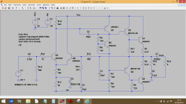
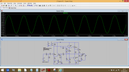
This shows the basics of your amp as a simulation running at 12 ma bias (all the component references are to pot as I quickly adapted it from another design). Rigging the vbe multiplier up like this will allow full control of the bias.
This shows the basics of your amp as a simulation running at 12 ma bias (all the component references are to pot as I quickly adapted it from another design). Rigging the vbe multiplier up like this will allow full control of the bias.
Attachments
I will definitely follow your advice and install the potentiometer (one question though on how to install it, On the board they put both input and ground in the same place but that doesn't seem right to me. Can I just leave one pin out (ground) and only solder the input and output ? )
Last edited:
Trim pot wipers have a nasty habit of going intermittant or at least getting noisy over time. Think in terms of years or decades - once the pot is set and forgot. If the wiper and low side are connected together, it sets the maximum resistance that you can see even if the wiper makes bad contact. It can't go open circuit on you. For this same reason, always install the pot in the base-emitter side rather than the base-collector. A momnetary high impedance on the base-collector can take out the output stage. The same on the base-emitter is at least safe.
I will definitely follow your advice and install the potentiometer (one question though on how to install it, On the board they put both input and ground in the same place but that doesn't seem right to me. Can I just leave one pin out (ground) and only solder the input and output ? )
Yes, its as wg_ski explains. Ideally it should be 'fail safe' which placing the pot in the lower arm of the resistor chain achieves.
If you wire the pot with the middle lead going to the base and the 'right hand' lead going to the emitter (as you look down on a typical preset pot) then that will give increasing current with clockwise rotation of the pot. Leave the other leg free (edit... which isn't what wg_ski recommends. I've never had a bias pot fail tbh but the theoretical risk is there. So either way) But... check it before switching on that the preset is on its highest resistance. The values on the simulation I did looked about right which would suggest a 2k2 pot if the other resistor were say 1.2k.
I'm leaving for the week end but I'll take some time to read your answers thoroughly and see how I can apply this when I'm back.
I'm back. When I first read your two last messages I was very tired and didn't get it the first time but reading it again now it seemed very clear. I followed your steps and I managed to get around 6.3mV on one channel but the other still stays at 0 whatever the position of the pot. I checked the resistance and it is exactly the same as on the other side.
I'll have more time to look later...
So one channel now works OK and the bias adjusts up to 6.3mv as measured across either 0.27 ohm. That equates to around 22 milliamps which is OK.
The problem with the other channel could be in either the output stage or the vbe multiplier. If you measure the voltage across the vbe multiplier (from C to E) then it will probably be around 1.85 volts give or take for the good channel.
Does the bad channel see that same sort of voltage ? Does the voltage increase as the pot is turned ?
Yes one channel now works perfectly 🙂
Ok so yes I do have 1.8v on both vbe multipliers between c and e and when I turn the pot clockwise the voltage increases so that seems to be working.
Ok so yes I do have 1.8v on both vbe multipliers between c and e and when I turn the pot clockwise the voltage increases so that seems to be working.
A couple of possibilities then. Whatever you do, don't blow anything up 😉 but I'm a little puzzled that the good channel only goes to 22ma as a maximum.
With the amp OFF, can you double check something with the preset turned to the position that gives the highest bias current. With the preset in the full bias position, it should be shorting out the base/emitter junction of the vbe multiplier. Can you check that it is by doing a quick resistance check before we go any further.
I'm assuming you have replaced the two series diodes with a resistor like in the simulation diagram above.
22 mA isn't the maximum, that is what I get when the preset is at 450ohms, would higher be better ?
I will check that first thing tomorrow.
In the case of my amp there always have been resistors and no diodes so I didn't have to change anything.
I will check that first thing tomorrow.
In the case of my amp there always have been resistors and no diodes so I didn't have to change anything.
Ah I see. 22ma is fine, its a safe value and should ensure cool running.
The circuit works like this... you need enough voltage across the vbe multiplier to overcome the three combined base/emitter volt drops of the NPN driver and NPN output transistor together with the single PNP driver at the bottom. The magic number is around 0.6 volts for each. When that situation is reached the transistors begin to conduct and current flows.
So on the bad channel there is the possibility of either a problem with the vbe multiplier not allowing enough voltage to be developed across it or if the voltage is present and you can go even higher than 1.8 volts (say 2 volts) and still no current is flowing in the output transistors, then there is a problem with the outputs and/or drivers.
A useful check in the drivers and outputs is to measure the voltage across the base and emitter. If any transistor has more than around 0.7 to 0.8 then its either faulty or incorrectly connected.
Actually the problem wasn't very hard to find. One of the drivers had only 0.1v across b and e and the other one 1.2v. When I looked a little closer the circuit of the first one was damaged and its base wasn't disconnected. I tried to repair the circuit as good as possible and now it works fine, 6.5mV for each channel.
Thank you for all the wise words.
My father collected a lot of amps when he was younger but most have been just standing somewhere getting dusty and only a few are working so I might be back soon for a new project, although I'll probably get a little further on my own after this 🙂.
My father collected a lot of amps when he was younger but most have been just standing somewhere getting dusty and only a few are working so I might be back soon for a new project, although I'll probably get a little further on my own after this 🙂.
Hello friends. I have this amplifier, but the damn diagram print is very bad. Can someone help me? What are the Q810, Q804, Q807, Q805 and Q808 transistor codes. I think it's completely ashed, I think it was a little bit hurt before. Thank you for the help and support, Regards
Can't help with a better diagram I'm afraid but I think for something old like this you are probably better fitting more modern devices.
With a little squinting, but mainly using image enhancement (*), I reckon:Hello friends. I have this amplifier, but the damn diagram print is very bad. Can someone help me? What are the Q810, Q804, Q807, Q805 and Q808 transistor codes. I think it's completely ashed, I think it was a little bit hurt before. Thank you for the help and support, Regards
Q807/810 - 789 (presume BD789? could be 2SC789)
Q804/805 - 2SC372 or "9630" - can't find any matches for "9630"
The drivers, Q806/Q809 are 2SC1164 / 2SA961 I believe
(*) unsharp mask on the Gimp - first reduce contrast a bit, then unsharp, basically sharpens any slightly out-of-focus image.
With a little squinting, but mainly using image enhancement (*), I reckon:
Q807/810 - 789 (presume BD789? could be 2SC789)
Q804/805 - 2SC372 or "9630" - can't find any matches for "9630"
The drivers, Q806/Q809 are 2SC1164 / 2SA961 I believe
(*) unsharp mask on the Gimp - first reduce contrast a bit, then unsharp, basically sharpens any slightly out-of-focus image.
Thanks Bro,
vintage hifi Scott: Scott A426 amplifier, Featuring an elegant brushed aluminum facade, made in japan
There is an interesting stray information. However, it is not specified which material it depends on. What surprises me is that all output transistors are NPN. I thought it should be an exceptional NPN and PNP compared to the existing designs. When I worked a little on the schematic, I realized that there was no mistake here ... During the production of the 70s, I think the PNP transistor was higher paid, fix me if I am wrong?
Thank you
- Home
- Amplifiers
- Solid State
- Scott A 426