No, it was for educational value! Cliff is on a learning curve, in case you didn't notice.Presumably this is/was basically for the entertainment value of the project ?
He's not going to start out on his diy adventures by 'patching' a Focal Grande EM Utopia Evo III, is he! 😀
No, it was for educational value! Cliff is on a learning curve, in case you didn't notice.
He's not going to start out on his diy adventures by 'patching' a Focal Grande EM Utopia Evo III, is he! 😀
Well explained G.
We're all at different places on that knowledge/experience curve. 🙂🙁
That remains my advice.
Without knowing the exact specifications of the original positecs, you will not be able to source replacements.
I removed the positecs from my Mordaunt Shorts years ago and I still haven't managed to blow the darned drivers up!
Hi.
Please don't take this as "flogging a dead horse".
I've already decided to eliminate the positecs and they've already been removed.
Just thinking out aloud:
I've noticed these Mordaunt Shorts are a sealed box design.
The previous owner indicated that they have a distinct lack of bass reproduction.
While surfing youtube discussions it was indicated that bass drivers fitted in similarly sized cabinets might need more power to get comparable bass in sealed box vs baffled.
Do you think this is part of the reason Mordaunt Short fitted the positecs in this model?
Cliff
Quick answer - No! 
Mordaunt Short fitted Positecs because they knew that Joe Average would always turn the volume 'up to eleven' to see how loud his new speakers would go.
The resulting rate of return of blown tweeters (and even woofers) necessitated the fitting of these protection devices.
If the MS45Ti speakers in question had a distinct lack of bass reproduction, then either the bass driver surrounds were faulty or the previous owner was using them outside in free air!
These speakers should have good bass, but tighter and less resonant than that from a ported enclosure.
I once had to return a pair of ported MS 35Ti to the shop because, in my home situation, they produced an overly fullsome bass.
Remember that the room size and the speaker location within the room greatly influence the bass response.
Attachments

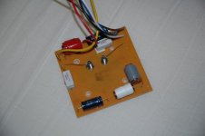
I attach the correct view of the MS45Ti crossover board. Looks like someone was trying to modify the one I attached previously.
Hi G.
The Mordaunt Shorts were finally reassembled.
Using information from this forum, the speaker cabinets were internally lined so there are no bare panels internally. Three chambers were created with the deadening material, a chamber for each of the 2 larger drivers, and the area behind the tweeter was filled.
Mastic was added to the larger drivers on the collar between the basket and the magnet ring.
The crossovers were fitted with equivalent PP caps and new resistors with identical values to the old.
The Positecs were removed and the circuit restored with wire.
End result, great dynamic range and overall great sound, but very very bright, to the point where at 40 on the amp dial it's uncomfortable to the ear.
So I think I need to add resistors to the crossover.
I've attached the photo of the crossover you attached earlier.
There are 2 resistors on the crossover.
Will I add resistors in parallel to the existing, or in series?
Should I add resistors to the existing resistor closest to one of the caps, or also to the resistor on its own?
cheers
Cliff
Attachments
I've re-attached a photo of the full crossover. I presume you remembered to include the off-board inductor in your re-build?The crossovers were fitted with equivalent PP caps and new resistors with identical values to the old.
End result, great dynamic range and overall great sound, but very very bright.
I can only see the value of one of the resistors (3.3Ω). Before I go any further, what is the value of the other one?
Attachments
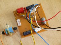
The other R is in series with the cap that is sitting across the upper mid/woofer, so its only a 3.3 in series with the tweeter (and the positec if still fitted)
Thanks afa. Do you have access to the schematic?
I believe the resistor at the top is part of an RC shunt over the twin series bass driver section.
The resistor at the left hand side is, as you say, the one in series with the tweeter.
Both resistors may be 3.3Ω!
@ Cliff
Experiment with the left hand side resistor value. You can substitute the current resistor with one of a larger value (e.g. 6.8Ω) or add another 3.3Ω in series with the current resistor.
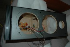
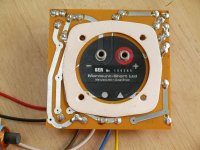
For completeness, I've added an internal shot and a shot of the track side of the crossover board.
It turns out that the MSB C woofer has a dc resistance of around 12Ω, so is nominally 16Ω impedance. Since the system impedance is nominally 8Ω, the woofers are running in parallel.
The upper woofer works all the way up to 4,000Hz where it crosses over to the tweeter (filter slope approx' 12dB/octave).
The lower woofer reproduces only the lower bass by virtue of a 200Hz, 6dB/octave low pass filter supplied by that off-board inductor.
Attachments
I dug out my old Mordaunt Short brochure and, since I've nothing better to do at the moment, will reproduce the specifications of the MS45Ti for Cliff's delight! 😀
Nominal Impedance = 8Ω
Sensitivity = 89dB/W/m
Amplifier Capability = 10W minimum
Acoustic Bandwidth = 55Hz - 20kHz @-3dB
Nominal Impedance = 8Ω
Sensitivity = 89dB/W/m
Amplifier Capability = 10W minimum
Acoustic Bandwidth = 55Hz - 20kHz @-3dB
Hi Galu, I had been gifted a pair earlier in the year and two of the bass drivers had surrounds coming away from the cone.
I fixed the surrounds and while i had them i roughly worked out the crossover and had a listen and a measure with my test gear....yes too bright, and from memory they had peaky response around 4-5K...dip around 3K, peak around 2K
Probably needed a crossover redesign, the tweeter (made by LPG? in Germany) had a shocking waterfall plot (tizzy titanium?), so probably needed better tweeters to perform well... wasn't economically (for me) to work on them.. so i ended up selling them "as is"
As you recommended to cliff, increasing the value of the 3.3 ohm would help tame the top end
Keep up the good work Galu
cheers, Arthur
I've re-attached a photo of the full crossover. I presume you remembered to include the off-board inductor in your re-build?
I can only see the value of one of the resistors (3.3Ω). Before I go any further, what is the value of the other one?
Hi.
Sorry for the delay.
The other is 2.2 ohm
Both are 5 watts.
Both positecs are gone, replaced with wire.
Last edited:
Thanks afa. Do you have access to the schematic?
I believe the resistor at the top is part of an RC shunt over the twin series bass driver section.
The resistor at the left hand side is, as you say, the one in series with the tweeter.
Both resistors may be 3.3Ω!
@ Cliff
Experiment with the left hand side resistor value. You can substitute the current resistor with one of a larger value (e.g. 6.8Ω) or add another 3.3Ω in series with the current resistor.
Hi G.
Sorry for delay in response.
I missed your instruction thinking the other resistors value might have had a bearing or your advice.
I have the following resistor spares.
8 x 100Ω 5W
2 X 2Ω 10W
1 X 18Ω 5W
I think I should make a purchase of Resistors to use for the MS's, but I should also put together a selection for adjusting my other projects.
I'll aim for 6.8Ω Resistors as per your instructions but was just hoping to learn ways of fitting resistors (series vs parallel) and how these affect outcomes?
For example, if I needed to add another 3.3Ω Resistor in series to achieve 6.6Ω resistance, could I have done that by adding, for example, a 2.3Ω & a 1Ω resistor (both in parallel) to the existing 3.3Ω resistor in series.
Also can I fit the additional resistor without solder (twist wires) for the test?
Thanks
C
The key word I used was 'experiment'! We don't know exactly how much total resistance is required in series with your tweeter to calm it down.
Try putting your 2Ω resistor in series with the existing 3.3Ω resistor and report back on the result. You don't have to solder for the experiment.
Tutorial:
Putting two resistors in series increases total resistance: Rt = R1 + R2
Putting two resistors in parallel decreases total resistance: Rt = (R1 x R2)/(R1 + R2)
The parallel case is better remembered as Rt = product of the two resistors divided by the sum of the two resistors.
Note: When putting two resistors in parallel, the total resistance is always less than the smaller of the two resistors.
The key word I used was 'experiment'! We don't know exactly how much total resistance is required in series with your tweeter to calm it down.
Try putting your 2Ω resistor in series with the existing 3.3Ω resistor and report back on the result. You don't have to solder for the experiment.
Tutorial:
Putting two resistors in series increases total resistance: Rt = R1 + R2
Putting two resistors in parallel decreases total resistance: Rt = (R1 x R2)/(R1 + R2)
The parallel case is better remembered as Rt = product of the two resistors divided by the sum of the two resistors.
Note: When putting two resistors in parallel, the total resistance is always less than the smaller of the two resistors.
Great tutorial.
I've saved it for future reference.
I'll add the 2Ω resistor in series as you've suggested and experiment from there.
Does it matter if some resistors are 5w and other 10w in the circuit?
Also, in which situations would you find it useful to add a resistor in parallel?
Is it a question of being able to reduce resistance by a calculated amount by making do with parts on hand?
Last edited:
Not in the case of attenuating your tweeter.Does it matter if some resistors are 5w and other 10w in the circuit?
You've got it. Wiring two resistors in parallel with each other is done when you need to make a resistor whose value is less than the smaller of the two resistors.Also, in which situations would you find it useful to add a resistor in parallel? Is it a question of being able to reduce resistance by a calculated amount by making do with parts on hand?
Not in the case of attenuating your tweeter.
You've got it. Wiring two resistors in parallel with each other is done when you need to make a resistor whose value is less than the smaller of the two resistors.
Thanks.
I'll get back to you with a sound report.
Hopefully I'll get it right with minimal experimentation.
You didn't answer my earlier question, Cliff.I presume you remembered to include the off-board inductor in your re-build?
Did you remember to re-install the stand alone inductor in series with the lower bass driver?
You didn't answer my earlier question, Cliff.
Did you remember to re-install the stand alone inductor in series with the lower bass driver?
Hi G
Sorry for experiencing long response times on occasion.
Just got home.
A mix of semi shift work, international time differences, need to retire early (somewhat sleep deprived), many hours spent working on two wheels, and online responses done by Desktop PC.
The stand alone inductor was definitely included in the re install.
I carefully documented all the crossover wiring for reassembly.
Thanks for being thorough
We wouldn't want to go down an experimental path only to find the stand alone inductor was causing the issues.
I'll be shortly putting an order through for a number of resistors.
cheers
Cliff
- Home
- Design & Build
- Parts
- Loudspeaker Driver Terminals???